My Strowger PBX · Volume 6
Troubleshooting
6.1 What This Volume Covers
This is the troubleshooting manual for the four-telephone exchange: how to find a fault quickly, the symptoms this exchange can show and where each one points, and the routine tests that catch trouble before a visitor does. It builds on the general step-by-step fault-finding in the history dive’s Volume 8, which follows a full switch train with selectors, and narrows it to this P-A-X: line circuits, two finder–connector links, the common equipment of Volume 4, the display of Volume 5, and line 66 to the crossbar exchange.
The method comes from Automatic Electric’s own maintenance bulletin for P-A-Xs (Technical Bulletin 565, 1961). Two of its sentences are worth keeping on the panel:
- “Always suspect the simple case of trouble first.”
- “Dirty contacts are electrically open contacts.”
Until the exchange is built, the tables below are drawn from the circuits in Volume 3, from the bulletins and from the history dive. The relay letters are those of Volume 3’s connector; check them against each switch’s drawing.
6.2 First: Who Is Affected?
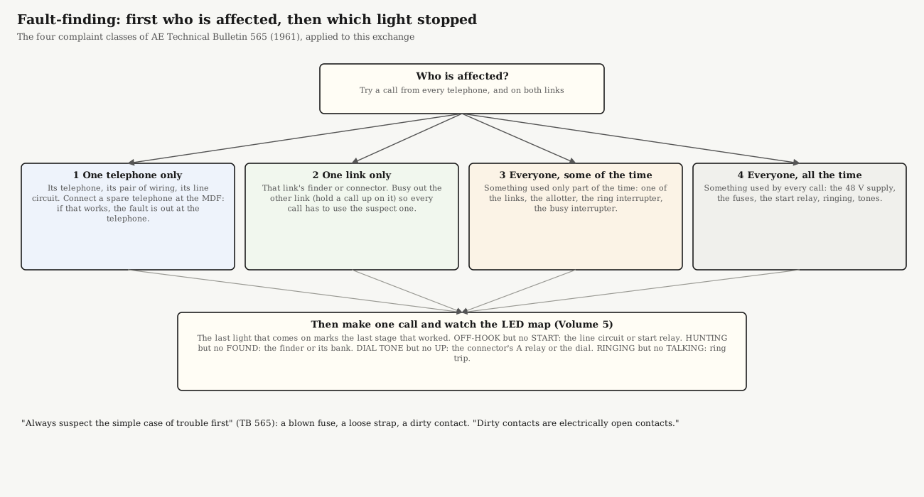
TB 565 sorts every complaint into four classes before anything is touched, because each class rules out most of the exchange:
Table 1 — TB 565 sorts every complaint into four classes before anything is touched, because each class rules out most of the exchange
| Class | Who is affected | Where the fault must be | First test |
|---|---|---|---|
| 1 | one telephone only | that telephone, its pair of wiring, or its line circuit; nothing shared | Connect a spare telephone at the MDF in place of the line. If it works, the fault is out at the telephone or its wiring; if not, it is the line circuit or its bank wiring |
| 2 | calls on one link only | that link’s finder or connector | Hold a call up on the other link, so every new call is forced onto the suspect one |
| 3 | everyone, some of the time | something used only part of the time: one link, the allotter, the ring or busy interrupter | Make calls repeatedly and note which link each one takes (the NEXT LINK light) |
| 4 | everyone, all the time | something every call uses: the supply, the fuses, the start relay, ringing, tones | Look at the fuse panel and the meters before anything else |
TB 565 recommends learning the exchange before the first fault: set up calls between two telephones, “delay between each step to note relay operation,” with the circuit drawing in hand, and repeat it until the sequence is familiar. On this panel, the LED map makes that easy.
6.3 Then: Which Light Stopped?
The display of Volume 5 is a fault-finder as well as a show. Make one call and watch the lights in order: the last light that comes on marks the last stage that worked, and the fault is in the next one.
Table 2 — Then: Which Light Stopped?
| Last light lit | What did not happen | Look at |
|---|---|---|
| nothing at all | the line relay did not operate | the telephone (class 1 test); the line’s fuse; L’s circuit through CO’s break springs |
| OFF-HOOK, but no START | the start relay | LEV.ST wiring; the start relay; its fuse |
| START, but no HUNTING | no finder started | the allotter and distributor; FST to the preselected finder; that finder’s fuse |
| HUNTING, but no FOUND | the finder did not stop on the caller | CF from the line equipment to the finder’s control bank; a dirty control wiper or bank contact; the finder’s cut-through relay |
| FOUND, but no DIAL TONE | the connector did not seize | the C lead from finder to connector; the connector’s A and B relays; the DT lead |
| DIAL TONE, but no UP when dialling | the connector’s A relay did not follow the dial | the dial (speed and ratio); a high-resistance or leaky loop; A |
| UP, but no ROUND | the rotary path | as history Volume 8: H, G, C, the off-normal springs, B and A |
| ROUND, then BUSY although the line is idle | the busy test saw ground on C | the called line’s CN lead and cut-off relay; a bank short |
| RINGING, but no TALKING when answered | ring trip | relay F; the ringing supply’s battery (Volume 4) |
6.4 Symptoms and Causes
6.4.1 Everyone, all the time (class 4)
Table 3 — Everyone, all the time (class 4)
| Symptom | Look at |
|---|---|
| No dial tone anywhere, nothing moves | The supply and the main fuse; the voltmeter should read about 49 V. The red FUSE ALARM shows a blown branch fuse; its flag shows which |
| No dial tone anywhere, but switches step | The DT lead: the dial-tone player, its 12 V supply, its transformer (Volume 4) |
| No telephone can be rung | The ringing generator, its fuse, the ring interrupter, the lock-out switch left in the off position |
| Busy tone missing everywhere | The busy-tone player, the busy interrupter, the BT capacitor |
| Hum on every call | A second ground point, or ripple on the supply: the + side is grounded at one point only (Volume 4) |
| The FUSE ALARM keeps coming back | A short downstream of that fuse: a pinched wire, a bank contact touching its neighbour, a shorted magnet |
6.4.2 Everyone, some of the time (class 3)
Table 4 — Everyone, some of the time (class 3)
| Symptom | Look at |
|---|---|
| Every other call fails | One link is faulty and the allotter alternates; force calls onto each link in turn (class 2) |
| Both finders hunt for the same call | The allotter or distributor: it must start only the preselected finder |
| Ringing sometimes doesn’t stop on answer | The ring interrupter’s battery-only position: without battery in the silent period, ring trip cannot act (Volume 4) |
| Calls drop during ringing | Ring trip tripping falsely: test with the Type 26A false-trip test (below) |
6.4.3 One link only (class 2)
The history dive’s Volume 8 table applies directly to the connector, symptom by symptom. The ones most likely on this exchange:
Table 5 — The history dive's [Volume 8](https://telephones.fubsypoly.com/telephone-switching-history/vol-8/) table applies directly to the connector, symptom by symptom. The ones most likely on this exchange
| Symptom | Look at |
|---|---|
| Dial tone doesn’t stop when dialling | The connector’s A relay not following the pulses; dial speed or ratio |
| Wrong number, double stepping | An overstepping rotary armature, vertical overthrow, excess vertical play; or the dial |
| Rings, but no ringback | With a pure sine-wave ringing generator, ringback can be faint by design (Volume 4); otherwise H and F contacts |
| Answered, but no speech | The connector’s two talk capacitors; the battery-feed relay’s windings and contacts |
| A switch won’t release | Mechanical first: release armature, link, helical spring; then off-normal and release-path contacts. In this AE connector, release needs both parties to hang up (Volume 3); one handset left off holds the link, which is normal |
| The finder releases at once | The holding ground on C from the connector’s B relay |
6.4.4 One telephone only (class 1)
Table 6 — One telephone only (class 1)
| Symptom | Look at |
|---|---|
| Can’t call out, can be called | The line relay L, or the LEV.ST/CF wiring of that line |
| Can call out, can’t be called | Its connector bank position: the CN lead and bank wiring (level = first digit, contact = second) |
| Every idle finder steps to this line and stays | Its line-and-cut-off relay: dirty or shorted contacts, or the relay not operating fully. “When only one subscriber’s telephone is affected, the most probable trouble is the L relay” (history Volume 8) |
| Always busy | Its cut-off relay stuck, or ground on its CN lead |
| Rings weakly, or not at all | The telephone’s ringer and its capacitor; the ringer connection in the set (TB 565, figure 3); test the set on the RS 43-114 |
6.4.5 Line 66 and the crossbar exchange
Table 7 — Line 66 and the crossbar exchange
| Symptom | Look at |
|---|---|
| Crossbar telephones dial 9 but hear no Strowger dial tone | Line 66 here, exactly as a class 1 fault: its line relay, bank wiring, fuse. Then the crossbar side (My Crossbar PBX, Volume 3) |
| 66 never answers | The crossbar trunk circuit’s ring detector; whether the crossbar exchange is powered |
| A call to 66 rings the wrong crossbar telephone | The selector switch on the crossbar panel |
6.4.6 The display
Table 8 — The display
| Symptom | Look at |
|---|---|
| A light never comes on | Its LED, its 12 V resistor, the opto on its board; then the −48 V tap (resistor, reverse diode, connection across the right coil) |
| A light stays on | A shorted opto transistor; or the relay really is operated, which is itself a fault to chase |
| A counter miscounts | Contact bounce on the magnet tap, or the counter not clearing at release |
| The exchange misbehaves only when the display is connected | The display has found a path into the exchange: check that no part of the 12 V side touches the ground bar or −48 V |
6.5 Tools
- A test lamp. TB 565’s basic instrument: clipped to a −48 V fuse and touched along a circuit contact by contact, it lights wherever battery is present; clipped to ground, it shows where ground is. The first contact where it stops lighting is the open one. A multimeter on DC volts does the same job.
- A hand test telephone with clips, to listen for dial tone, busy tone and ringback anywhere, and to seize a connector through a test jack.
- The Type 26A switch tester, for connector tests no handset can make, above all ring trip and false trip: 1600 Ω must trip; 2300 Ω must not, for a battery-connected generator (2200 Ω for superimposed ringing, 2500 Ω for a ground-connected one), per history Volume 8. Run it with the supply at 48.5–50 V. AE Type 26A Switch Tester.
- The RS 43-114 telephone tester, for every telephone: dial speed and break ratio, ringer, transmission (RS 43-114 dive).
- Cleaning and adjusting tools: a contact burnisher, relay adjusting pliers, feeler gauges, and the lubricants of AE Bulletin 505, sparingly (Volume 2).
6.6 Routine Tests
TB 565 recommends scheduled tests “at relatively long intervals and with simple test equipment,” and judges that “the careful and regular testing of each piece of equipment once every second month should be sufficient.” The small-P-A-X instructions add monthly checks of the alarm and the power supply (Operating Bulletin 32A1). For a display exchange:
Table 9 — TB 565 recommends scheduled tests "at relatively long intervals and with simple test equipment," and judges that "the careful and regular testing of each piece of equipment once every second month should be sufficient." The small-P-A-X instructions add monthly checks of the alarm and the power supply ([Operating Bulletin 32A1](https://telephones.fubsypoly.com/library/operating-bulletin-32a1-installing-and-operating-instructions-for-type-3/)). For a display exchange
| When | Test | How |
|---|---|---|
| Each time it is shown | Every telephone calls every other | 22, 33, 44, 55 in turn; two calls at once; a busy call; a call to and from the crossbar exchange |
| Monthly | Power and alarm | Read the voltmeter (about 49 V). Prove the fuse alarm: TB 565 shorts each fuse alarm strip to its bus bar and checks the signal; on this panel, fit a flagged fuse in a spare position and watch the red lamp |
| Every two months | Finders | TB 565 shorts the finder group’s test jacks so the unoccupied finders “step vertical and rotary to the eleventh position and release”; here, lift each handset in turn and watch each finder find it |
| Every two months | Connectors: vertical and rotary | With a test telephone on the connector’s test jack, listen for dial tone, dial to a vacant position, touch the control wiper with a test lamp to battery and listen for busy tone; check release (TB 565 §9.3.1) |
| Every two months | Connectors: switch-through | Dial a telephone, check ringback, answer, check ringing stops and speech both ways, check release (TB 565 §9.3.2); then the Type 26A’s ring-trip and false-trip tests |
| Yearly | Clean and oil | TB 565: clean and oil the Strowger switches once a year, busying out the link first; clean bank contacts with the bank-cleaning tool; burnish relay contacts only when dirty, never with a rough tool |
Keep a log. TB 565 notes that it “is often helpful to keep records of common trouble,” and on an exchange this small, the log will soon show which relay is the weak one.
6.7 In the Reference Library
- Technical Bulletin 565: General Maintenance of P-A-X’s: complaint classes, the test lamp, routine tests.
- Operating Bulletin 32A1: a small P-A-X’s maintenance schedule.
- AE Training Bulletin 807: The Connector and 821: Linefinder Switches: the circuits behind every symptom.
- AE Standard Adjustments and GSP 230-005-702, wiper adjustment: the mechanical adjustments.
- AE Bulletin 505: Lubrication.
Sources
- Automatic Electric, Technical Bulletin 565: General Maintenance of P-A-X’s (1961), sections 5, 6 and 9, Reference Library.
- Automatic Electric, Operating Bulletin 32A1, maintenance schedule, Reference Library.
- Telephone Switching History, Volume 8 (fault-finding by symptom, the Type 26A’s ring-trip values, test equipment), on this site.
- My Strowger PBX, Volumes 3–5, on this site.