My Strowger PBX · Volume 3
Wiring
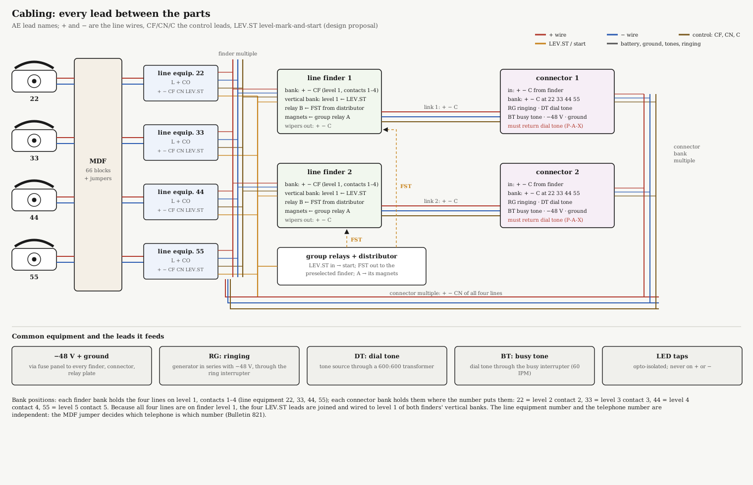
3.1 What This Volume Covers
Volume 1 showed what the exchange needs. This volume shows how the parts connect: which wire goes where, what each lead does, and how a call travels along them. It has three parts:
- The leads: the small vocabulary of wires every step-by-step exchange is built from.
- The diagrams: the cabling diagram above, the line circuit, the bank maps and the power distribution.
- A call through the wires: one call from 22 to 44, lead by lead, from the lifted handset to the last switch dropping home.
This is the system wiring. It holds for any Automatic Electric finder-connector P-A-X, because every AE line finder, connector and line relay uses the same leads for the same jobs. What it cannot give is the spring-by-spring wiring inside each switch and relay set. That comes from the circuit drawing (the H- number) of each part actually bought, and those drawings go in the Reference Library as the parts arrive. Where Western Electric parts are used, the same leads appear under Bell System names: tip, ring and sleeve for AE’s +, − and C.
3.2 The Leads
Automatic Electric’s drawings name the two line wires + and −. The + wire is the side fed from ground and the − wire the side fed from battery, the two wires the Bell System calls tip and ring. Three more leads per line do all the control work. AE’s linefinder bulletin names them (Bulletin 821):
Table 1 — Automatic Electric's drawings name the two line wires + and −. The + wire is the side fed from ground and the − wire the side fed from battery, the two wires the Bell System calls tip and ring. Three more leads per line do all the control work. AE's linefinder bulletin names them ([Bulletin 821](https://telephones.fubsypoly.com/library/ae-training-bulletin-821-linefinder-switches-1957/))
| Lead | Runs between | What it carries |
|---|---|---|
| + and − | telephone, line equipment, finder banks, connector banks | the talking path; the dial pulses; ringing to the called telephone |
| CF (linefinder control) | line equipment → control bank of every line finder | battery through the cut-off relay when the line is calling: the finder hunts for it |
| CN (connector control) | line equipment → control bank (C contacts) of every connector | battery through the cut-off relay when the line is idle; ground when it is busy |
| LEV.ST (level marking and start) | line equipment → the finders’ vertical banks and the group relays | ground when a line on that level calls: marks the level and starts a finder |
| C (control) | finder wipers → connector | the holding lead of a link: ground on it holds the finder and the calling line’s cut-off relay |
| FST (finder start) | group relays, through the distributor → one finder | starts the preselected finder |
Connector Bulletin 807 sets out the three uses of the control lead at the connector bank: “To test whether the called line is busy. To cut off (during a call to the line) equipment used when the subscriber makes a call from his telephone. To mark the called line ‘busy’” (Bulletin 807). It calls lead C “analogous to the manual-switchboard ‘sleeve’,” and it never leaves the exchange.
The common leads come from the shared equipment: −48 V and ground to everything, and three to the connectors, RG (ringing through the interrupter), DT (dial tone) and BT (busy tone). Bulletin 807 describes a connector shelf the same way: the switches’ own bank leads “plus a few other leads for battery, ground, ringing current, busy tone, etc.”
3.3 The Line Circuit
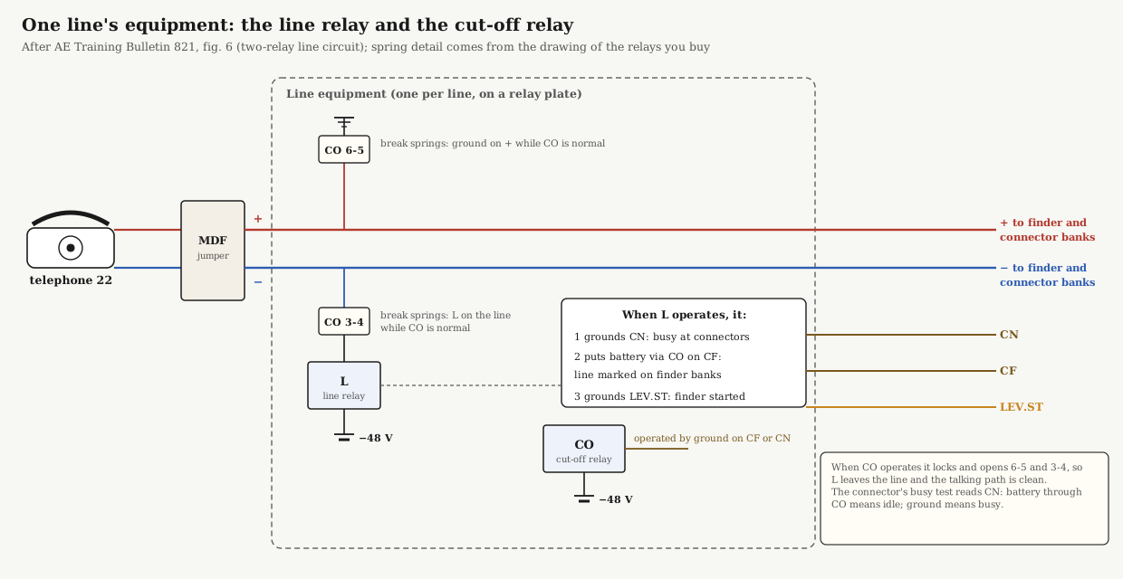
Every telephone has one line equipment: a line relay and a cut-off relay on a shared relay plate. Bulletin 821 lists its four jobs. When the handset is lifted it “(1) busies that line to other calls, (2) marks the position of the calling line in the linefinder banks, (3) signals the group relays to start a linefinder, and (4) when a linefinder has found him, clears the line of attachments. Also, when a subscriber is called, his line equipment clears his line of attachments.”
The circuit is two relays:
- L, the line relay, sits across the line through two break springs of the cut-off relay: “ground through relay CO contacts 6-5, + line, subscriber’s telephone, − line, and relay CO contacts 3-4” to L and battery (Bulletin 821, 4.1). A lifted handset closes that loop and L operates.
- CO, the cut-off relay, has one end at battery and its other end on the control leads. Ground from a finder (on CF) or from a connector (on CN) operates it. CO locks and opens its springs 6-5 and 3-4, which takes L and its ground off the line. From then on the + and − wires carry only the call.
The line equipment’s number has nothing to do with the telephone number. Bulletin 821: “Through the distributing frame, any outside line may be connected to any line equipment.” On this panel the MDF jumper is what makes a telephone 22.
3.4 The Banks
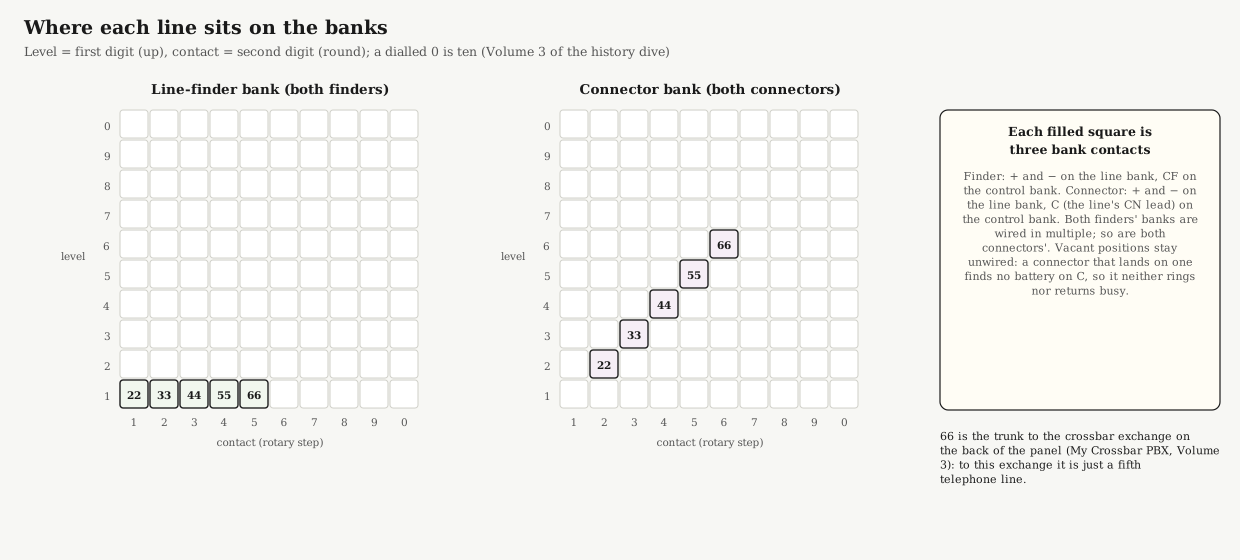
Each filled square on the bank maps is three wires: the line’s + and − on the line bank, and its control lead (CF on a finder, CN on a connector) on the control bank. Each set of three is multipled: the same three wires visit the same position on both finders, and the same position on both connectors. That multiple is the whole secret of a step-by-step exchange. Any finder can reach any caller, and any connector any called line, because every bank holds the same lines in the same places.
Two choices keep this exchange simple:
- One finder level. All four lines are on finder level 1, so a finder only ever climbs one step. It also means the four LEV.ST leads can be joined into one and wired to level 1 of both finders’ vertical banks. (On a full 100-line finder each level has its own LEV.ST lead; Bulletin 821 adds a 2000 Ω resistor in each so that only the calling line’s level carries a direct ground.)
- Numbers on the diagonal. 22, 33, 44 and 55 each take one connector level, so each call has a visibly different climb. The cost is four levels of connector bank cabling instead of one. A vacant position needs no wiring: a connector that lands on one finds no battery on C, so it neither rings nor returns busy.
3.4.1 Line 66: the trunk to the crossbar exchange
The crossbar exchange on the back of the panel (My Crossbar PBX) joins this one through a trunk, and to this exchange the trunk is simply a fifth telephone line, number 66. It gets the same line equipment as the other four (a line relay and a cut-off relay), finder bank position level 1 contact 5, and connector bank position level 6 contact 6, wired in multiple like the rest. A crossbar caller who dials 9 reaches this exchange as if line 66 had lifted its handset, hears this exchange’s dial tone and dials 22–55; a caller here who dials 66 rings the crossbar exchange’s trunk, which answers and rings a chosen crossbar telephone (My Crossbar PBX, Volume 3).
3.5 Power Distribution
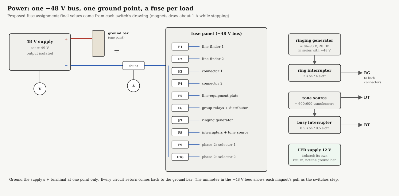
Four rules, each from the history dive’s Volume 8 or the bulletins:
- Positive ground, at one point. The office battery is −48 V with its positive side grounded. Every return comes back to the one ground bar.
- A fuse per load. One fuse per switch and per relay group, so a fault takes out one part and the fuse panel shows which. The proposed assignment is on the diagram. The final fuse values come from each switch’s drawing, since a magnet draws about an ampere while it steps.
- Ringing on battery. The ringing generator is wired in series with −48 V, so the connector’s ring-trip relay sees direct current between rings as well as during them. That is what lets ringing stop the moment the called handset is lifted.
- The display stays out. The LED supply is separate and isolated. Every LED senses a spare contact through an opto-isolator, and none touches + or −.
3.6 A Call Through the Wires: 22 Dials 44
This is the call from Volume 1’s walk-through, followed lead by lead. The relay letters inside the line finder and group relays are Bulletin 821’s; those inside the connector are the history dive’s Volume 5, after Bulletin 807 and Doug Kerr’s connector paper. The relays in the switches actually bought may carry other letters, but they do the same jobs in the same order.
3.6.1 The handset lifts
Lifting the handset at 22 closes the loop: ground through CO springs 6-5, the + wire, the telephone, the − wire, CO springs 3-4 and the coil of L to battery. L operates, and with its contacts it:
- grounds CN, so both connectors now see line 22 as busy;
- puts battery through the CO coil onto CF, so line 22’s contact on the control bank of both finders is now “marked”;
- grounds LEV.ST, marking level 1 on both finders’ vertical banks and starting the group relays.
On the panel: the off-hook LED for 22 lights. Nothing has moved yet.
3.6.2 A finder is started
Ground on LEV.ST operates the group relays’ C relay, which tells them a finder of this group must hunt. Through the FST wiper of the distributor, the group relays operate relay B of the preselected finder, the one the distributor is resting on. That finder’s B relay connects its vertical and rotary magnets to the group relays: “since only the preselected linefinder’s vertical and rotary magnets are connected to the group relays, the preselected linefinder is the only one that can be stepped” (Bulletin 821, 4.2).
3.6.3 The finder hunts up, then round
Group relay A and the finder’s vertical magnet drive each other: the magnet lifts the shaft one step and opens its interrupter springs, which release A; A releases the magnet, whose springs reoperate A. The shaft climbs one level per cycle until the finder’s vertical wiper touches the level-1 contact grounded by LEV.ST. Relays M and P then hold the vertical magnet and “transfer the pulsing path from vertical to rotary magnet.” The same self-interrupting cycle now drives the rotary magnet, one contact per step, until the control wiper touches the contact carrying battery from line 22’s CF lead (Bulletin 821, 4.3–4.4).
On the panel: finder 1’s hunting LED lights, and the shaft visibly rises one step and turns to contact 1.
3.6.4 The finder stops and cuts through
Line 22’s cut-off relay CO operates in series with group relay J or K, which opens the rotary magnet’s circuit so the finder stops dead on the line. CO locks and opens springs 6-5 and 3-4: L leaves the line and releases, and its ground leaves LEV.ST. The finder grounds CF (and through the line equipment CN), so line 22 stays busy. The finder then switches 22’s + and − wires and its own C lead through to its connector and steps the distributor to the next idle finder, ready for the next caller.
On the panel: the finder’s found LED lights; the next-link LED moves to link 2.
3.6.5 The connector seizes and sends dial tone
The loop now runs from 22 through the finder wipers into connector 1. Its A relay operates across the loop and feeds the caller’s battery. A operates the slow-release B, which “ground[s] lead C to hold” everything behind it: the finder and line 22’s cut-off relay (Bulletin 807, seizure). The connector is now busy to everyone else and ready for pulses.
This is the one place where a P-A-X differs from a central office. In a large office the connector never sends dial tone: the first selector, earlier in the train, has already done it. In a finder-connector P-A-X there is no selector, so “the connector returns dial tone to the subscriber” (Bulletin 818). The connectors for this panel must be P-A-X connectors that do this, or each link needs the small dial-tone relay that AE’s 10-line P-A-X used, returning tone “through a capacitor” (E-75159). Dial tone enters on the DT lead.
On the panel: the dial-tone LED for link 1 lights, and 22 hears dial tone.
3.6.6 The first digit: four pulses up
Each dial pulse opens the loop for about 60 milliseconds. A releases on every break and reoperates on every make; slow-release B holds through the whole train. Each release of A sends one pulse through C to the vertical magnet: four pulses, four steps up, to level 4. When the train ends, C (also slow to release) drops out and switches the next train to the rotary magnet.
On the panel: the pulse LED blinks four times while the connector shaft climbs four levels.
3.6.7 The second digit: four pulses round
The next four pulses step the rotary magnet: the wipers turn onto contact 4 of level 4, line 44’s position. During rotation the line wipers are disconnected, so they do not click across other lines’ + and − on the way (Bulletin 807, summary of functions).
3.6.8 The busy test on C
With the wipers on 44, relay E times a test of the C wiper, which now rests on line 44’s CN lead:
- Ground on C: line 44 is busy. Relay G operates, locks and returns busy tone from the BT lead. Nothing more happens until 22 hangs up.
- Battery through 44’s cut-off relay: line 44 is idle. Relay H operates and locks, puts ground on C, and grounds line 44’s control lead, which does two things at once. It operates 44’s own cut-off relay, taking 44’s line relay off the line so 44’s answer will not start a finder. It also marks 44 busy at every other connector’s bank.
On the panel: the testing LED lights briefly, then busy or ringing.
3.6.9 Ringing and ringback
H connects the RG lead, ringing in series with battery through the interrupter, to line 44 through the winding of the ring-trip relay F. 44’s bell rings two seconds on, four off. Ringback reaches 22 from the same ringing current through capacitors in the connector, so the caller hears the ring in step with the bell.
On the panel: 44’s ringing LED flashes in time with the bell.
3.6.10 The answer
When 44’s handset is lifted, direct current flows through its loop and the ring-trip relay F. F cannot operate on the alternating ringing alone, because the ringer’s capacitor blocks DC, but the battery in the ringing lead flows the moment the loop closes, between rings or during one. F operates, locks, cuts off ringing and ringback, and switches 44’s + and − through to the talking path. Relay D feeds battery to 44 and reverses 22’s battery to signal the answer. The connector’s two battery feeds and its two capacitors keep each side’s direct current separate while the voice passes between them.
On the panel: the answered LED lights, then talk.
3.6.11 Hang-up and release
When 22 hangs up, its loop opens for good: A releases, and after its slow-release time so does B. In the Automatic Electric connector of the USAF course, that is not yet the end. Relay D, held by the still-lifted handset at 44, keeps F and H operated and the control lead grounded: “The connector cannot be released by the release magnet until both parties hang up” (history dive, Volume 5). When 44 hangs up too, D releases and ground leaves lead C. The finder’s holding relays release, both lines’ cut-off relays release, and the release magnets knock out the detents. Each shaft spins home on its spring and drops to normal under its own weight. Both line equipments are back in the idle state of step 1, ready for the next lifted handset. (The connectors actually bought may release on the caller alone; their drawings will say.)
On the panel: every LED goes out as the two shafts drop.
3.6.12 Two calls at once
While 22 and 44 talk, link 1 holds lines 22 and 44 busy through their CN leads, and the distributor already points to finder 2. When 33 lifts, finder 2 hunts for 33 and connector 2 serves it. 33 can dial 55 and the second call sets up exactly as the first did, on its own link. If 33 dials 22 or 44 instead, connector 2 finds ground on C and returns busy tone.
3.7 Wiring It Up, in Order
Wire and test in stages, so each stage is proved before the next depends on it:
- Power and ground only. Supply, ground bar, fuse panel, meters. Set the supply to about 49 V. Check polarity at every fuse output with nothing connected.
- MDF and line equipment. Telephones to the MDF, jumpers to the line equipment, line equipment to power. Lift each handset in turn and check with a meter: L operates, LEV.ST goes to ground, CN goes to ground, CF shows battery. Hang up and check that everything returns.
- Bank multiples, unpowered. With a meter on continuity, check every position: 22’s + and − from the MDF to finder level 1 contact 1 on both finders and to connector level 2 contact 2 on both connectors, and the same for 33, 44 and 55, including the control leads. Any wrong bank position shows up here, not halfway through a call.
- Finders and group relays. Power one finder. Lift each handset in turn and watch it climb one level and turn to the right contact. Then the second finder, then both: lift two handsets and check that each finder takes one.
- Connectors. Power one link. From 22, dial each number and watch the climb and the turn; check dial tone, busy tone (with the called handset lifted), ringing and answer. Then the second link, then two calls at once. The Type 26A switch tester can run a connector’s routine tests in place once its cords are made.
Use 24 AWG switchboard cable for the bank multiples and links, heavier red and black wire for battery and ground, and keep the ringing lead’s run away from the talking pairs. Label every cable at both ends. A wiring fault in a step-by-step exchange is almost always a single wire on the wrong bank contact, and the bank maps above are the record to test against.
3.8 In the Reference Library
- AE Training Bulletin 821: Linefinder Switches: line equipment, group relays, distributor and the finder’s hunt, with the leads used here.
- AE Training Bulletin 807: The Connector: the control lead, seizure, pulsing, busy test, ringing and release.
- AE Training Bulletin 818: P-A-X’s: the finder-connector P-A-X, where the connector returns dial tone.
- E-75159 10-Line Isolated PAX: a complete small exchange’s circuit explanation, including dial tone through a capacitor (a 24-volt design).
- Technical Bulletin 565: General Maintenance of P-A-X’s.
Sources
- Automatic Electric, Training Bulletin 821: Linefinder Switches (1957), sections 3.1–3.3 and 4.1–4.4, Reference Library.
- Automatic Electric, Training Bulletin 807: The Connector (1958), Reference Library.
- Automatic Electric, Training Bulletin 818: P-A-X’s with P-A-B-X Appendix (1959), Reference Library.
- Automatic Electric, circuit explanation E-75159 (1944), Reference Library.
- Telephone Switching History, Volume 5 (connector relays, ring trip, tones) and Volume 8 (power), on this site.