My Strowger PBX · Volume 1
The System
1.1 What It Is
This is a small private automatic exchange (a P-A-X in Automatic Electric’s language) built from real Strowger step-by-step switches, with four telephones that can all call one another. I’m building it on a single upright panel, 3 by 4 feet, of plywood or clear acrylic, mounted on rails with wheels so it can roll to wherever people are. Nothing in it is hidden: a visitor lifts a handset and watches the exchange answer, hears dial tone, dials, and watches the switches climb and turn to find the telephone being called.
The design follows the way Automatic Electric built its own small P-A-Xs. AE’s Training Bulletin 818 describes the pattern: when a caller lifts the handset, “the line equipment busies his line to all other callers, activates the group relays, and marks his line contacts on all the linefinder banks. The linefinder then searches out the marked line and puts thru a connection to a connector.” A distributor “common to all linefinders in a group determines which idle finder will serve the next call.” The connector “returns dial tone to the subscriber,” and “subscriber dialing steps the Strowger connector in two directions. The first digit steps the mechanism vertically and the second dialed digit rotates the mechanism to the called line’s terminal banks” (AE Training Bulletin 818). That is exactly the system on this panel, at its smallest useful size.
1.2 What the Visitor Sees
The goal is a demonstration that explains itself. With the LEDs on the panel and the switches under clear covers, a visitor should be able to watch every one of these stages happen:
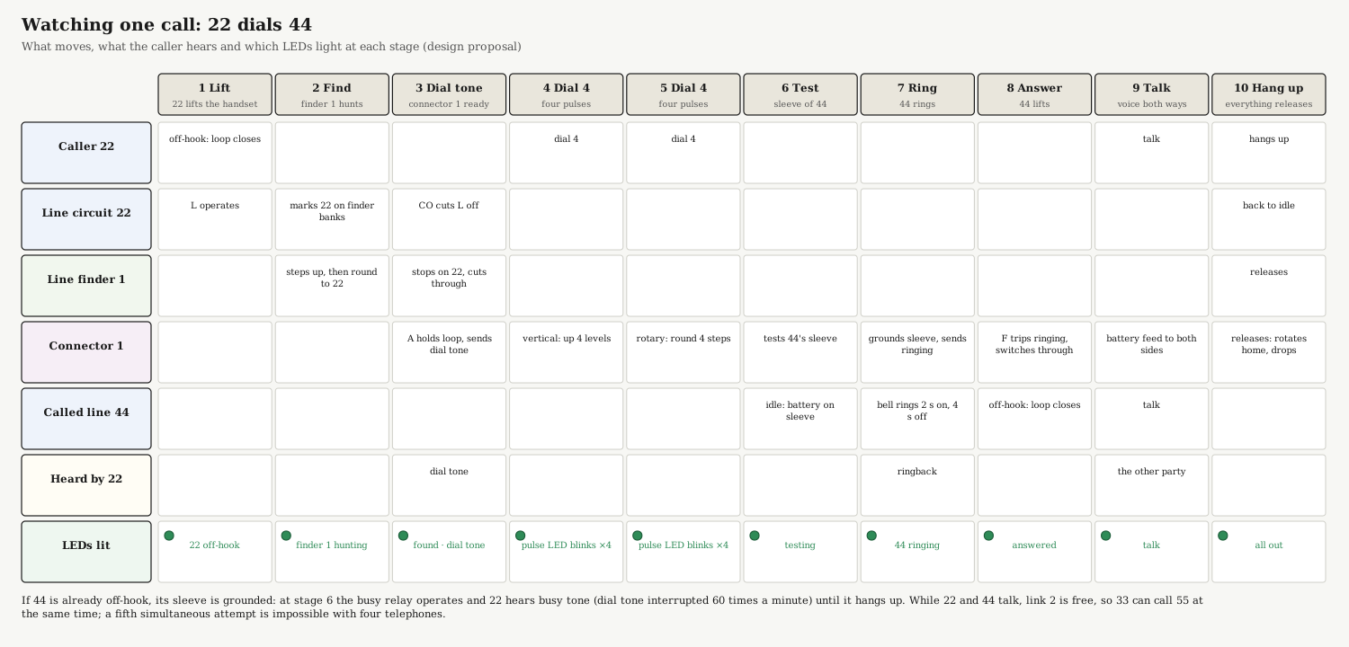
- Lift the handset. The line relay operates and the line’s LED lights. Nothing has moved yet.
- The finder hunts. A line finder steps up to the caller’s level, then turns along it until its wipers land on the caller’s line. It stops, and the caller’s line circuit cuts its own relay off.
- Dial tone. The connector paired with that finder holds the line and sends dial tone.
- Dial the first digit. The connector’s shaft climbs one level per pulse.
- Dial the second digit. The shaft turns one contact per pulse, to the called line.
- Busy or free. The connector tests the called line’s sleeve. If the line is in use, the caller hears busy tone. If it is free, the connector rings it and the caller hears ringback.
- Answer. Lifting the ringing handset trips the ringing, and the connector switches the two lines through to talk.
- Hang up. Each switch rotates back to its home position and drops to normal, and every LED goes out.
Then two people can call two others at the same time, and the second call takes the other link while the first is still talking.
1.3 The Block Diagram
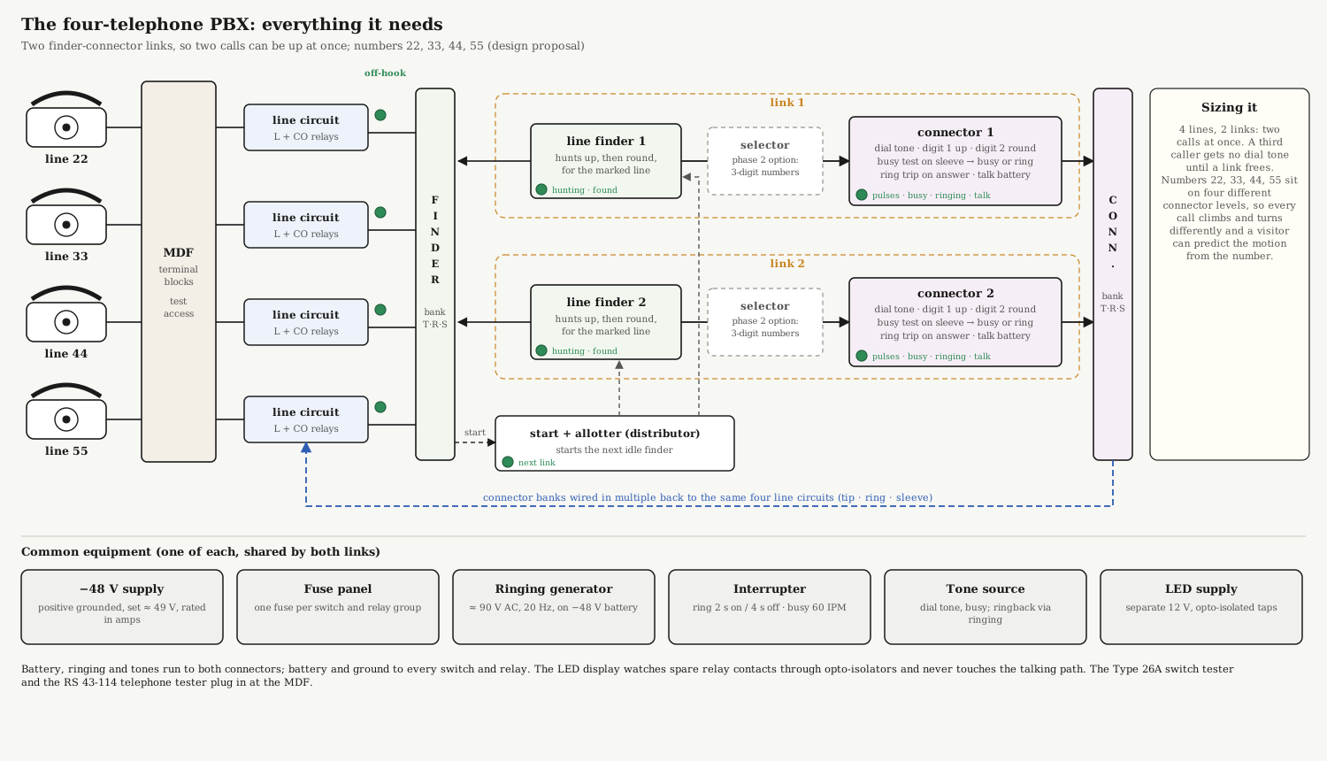
Reading the diagram from left to right:
- Telephones and the MDF. Each telephone’s line arrives at a terminal block, the panel’s main distributing frame. It is the one place where every line can be disconnected, cross-connected or tested, and where the switch tester and the telephone tester plug in.
- Line circuits. Each line has a line relay (L) and a cut-off relay (CO). L operates when the handset is lifted, marks the line on the line-finder banks, and starts the allotter. CO operates when a finder or connector seizes the line and takes L off it, so the line relay does not stay in the talking path. AE’s 10-line P-A-X did both jobs with one line-and-cutoff relay per line (E-75159).
- Start and allotter. With two links, something must decide which idle finder answers the next call, and stop both finders from chasing the same caller. AE’s 10-line P-A-X did it with two relays, “so arranged that when both finder switches are idle, the first finder is selected and the second finder switch cannot be started while the first switch is hunting” (E-75159). A rotary distributor does the same job on larger systems; if my “distribution switch” is one, it can take this place.
- Two links. Each link is a line finder wired to a connector. The finder’s bank is wired in multiple to all four lines, so either finder can reach any caller. The number of links sets how many calls can be up at once: two links, two calls.
- Connector banks. Both connectors’ banks are wired in multiple back to the same four lines (tip, ring and sleeve). That multiple is how either connector reaches any called line, and the sleeve lead is how each connector sees that a line is busy.
- Common equipment. One −48 V supply (positive side grounded), a fuse panel, one ringing generator with an interrupter, one tone source and a separate low-voltage supply for the LEDs serve both links.
1.4 The Numbers: 22, 33, 44 and 55
With a connector, the number is the position. The first digit raises the shaft that many levels and the second turns it that many contacts, so a two-digit connector reaches a hundred numbers “with no arithmetic at all” (history dive, Volume 3). AE’s own small P-A-Xs used two-digit numbers; for its Type 25, “usually numbers from 11 to 85 are assigned” (Bulletin 818).
Any four numbers on the connector bank would work. The proposal here is 22, 33, 44 and 55:
- Each number sits on a different level, so every call makes a visibly different climb, and a visitor told the number can predict the motion before it happens: dial 44 and the shaft goes up four and round four.
- Doubled digits are easy to remember and easy to dial.
- The longest number, 55, is ten pulses in all: about one second of pulsing at the standard 10 pulses a second, plus the pause between digits.
The alternative is four numbers on one level (21, 22, 23, 24). It saves bank wiring, since only one level of each connector bank needs cabling, but every call then climbs the same two steps and only the rotary motion differs. The finder side does not care: the four lines can sit on the first four contacts of one finder level whatever their numbers are, which keeps the hunt short.
1.5 Two Digits Now, a Selector Later
A finder and a connector are the smallest real step-by-step link. A selector in between adds the one motion a connector never makes: after its digit, a selector hunts along the level by itself, looking for a free connector, and skips any that are busy (history dive, Volume 3). It also adds a digit, so the numbers would become three digits (for example 222, 233, 244, 255, with the selector taking the leading 2). Bulletin 818 describes exactly this growth step: AE’s Type 50 P-A-X put “selectors between linefinders and connectors” so a system could expand.
The first selector in my collection, an AE selector on circuit H-580059, is the obvious candidate. Its drawing (H-580059-A) calls it a “Selector Circuit, Local or Incoming, Battery Searching”: as a local selector it returns its own dial tone, it hunts for an idle connector by the resistance battery on the connector’s C lead, and it is rated for 45 to 52 volts, so it suits the panel’s 49 V. The panel layout keeps a space beside each link for one, so phase 2 needs no rebuilding: the finder’s output is re-cabled to the selector, and the selector’s level 2 to the two connectors.
1.6 How Big Is Each Part?
Table 1 — How Big Is Each Part?
| Part | How many | Why |
|---|---|---|
| Telephones | 4 | the brief |
| Line circuits (L + CO) | 4 | one per line |
| Line finders | 2 | one per link |
| Connectors | 2 | one per link |
| Selectors | 0 now, 2 in phase 2 | one per link, if added |
| Start and allotter | 1 set | chooses the next finder |
| −48 V supply, fuse panel | 1 each | shared |
| Ringing generator, interrupter | 1 each | shared |
| Tone source | 1 | dial tone and busy |
| LED display and its supply | 1 | separate from the exchange circuits |
With four telephones and two links, every possible pair of simultaneous calls can be set up. Congestion is still easy to show: while 22 is talking to 44, if 33 lifts and starts dialling, link 2 is in use, and a handset lifted at 55 in that moment gets no dial tone until a link frees. The line LED is lit, but no finder moves. That is a real step-by-step exchange’s behaviour when every link is busy.
1.7 The Panel
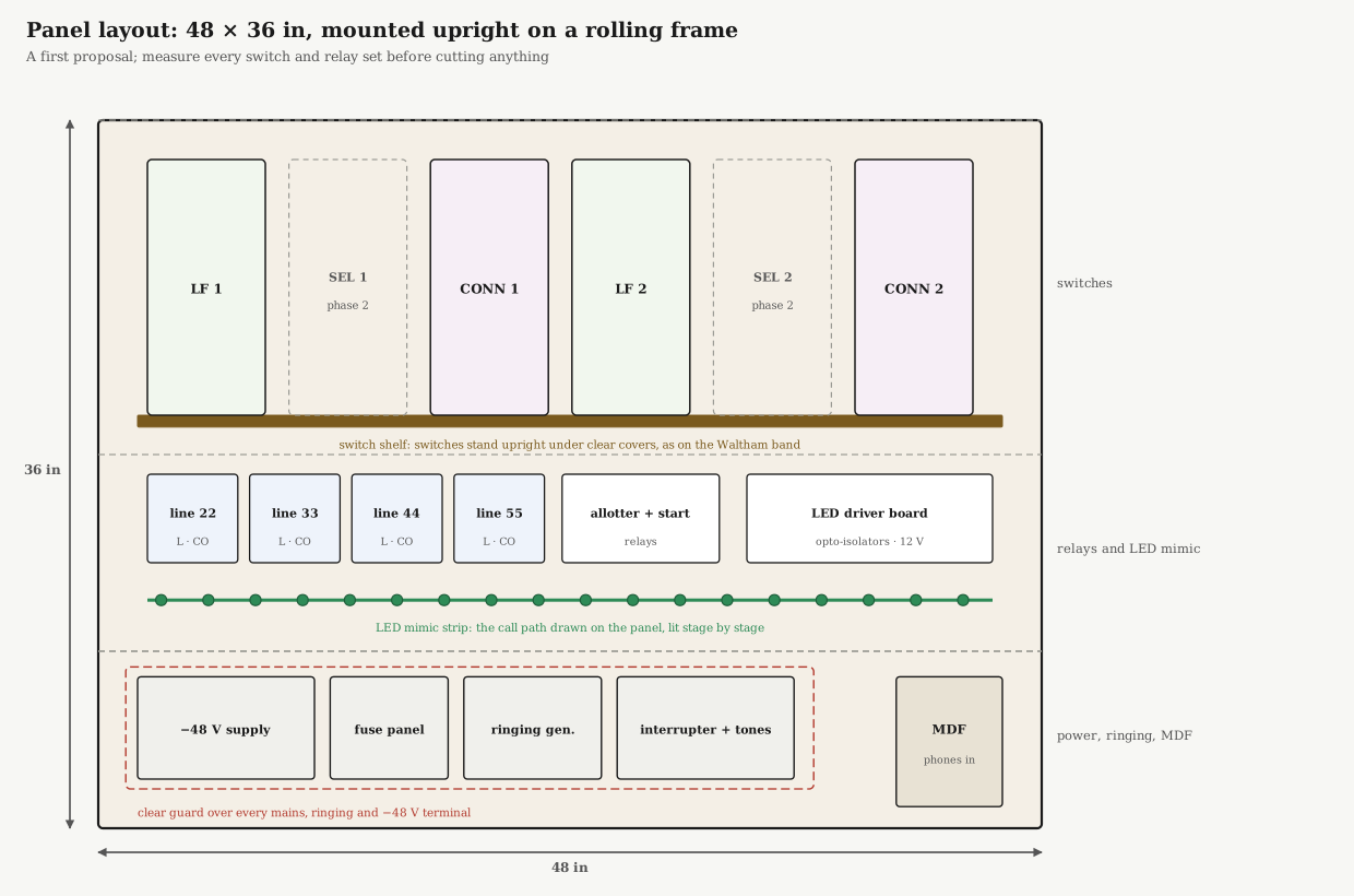
Two physical facts shape the layout:
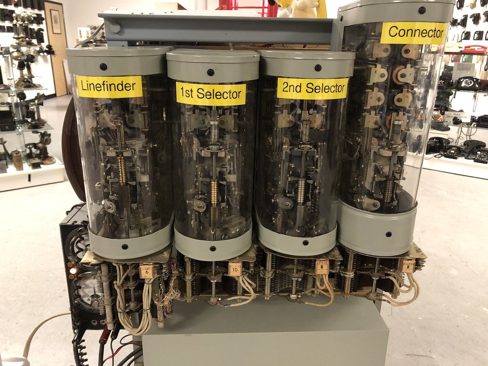
- The switches must stand upright. A two-motion switch releases by rotating home and then letting the shaft drop under its own weight to normal (history dive, Volume 3). Mounted any other way, it will not release. So the switches sit on a shelf in a row, exactly as on the Waltham band in the photograph at the top of this volume.
- Everything dangerous goes behind a guard. The exchange runs on −48 V, ringing peaks reach 175–190 V, and the power section connects to the mains. On a panel built to be looked at closely, every mains, ringing and battery terminal goes behind clear covers that people can see through and not touch.
The clear switch covers on the Waltham band are the look this panel aims for: each switch in its own transparent cylinder with metal end bands, labelled, the banks and cabling open beneath. How to make those covers is part of the aesthetics work still to come.
1.8 What Comes Next
The remaining volumes take the design from block diagram to working exchange:
- Volume 2, Bill of Materials: every part the panel needs, what is already in the collection and what has to be found.
- Volume 3, Wiring: the leads, the cabling diagram, the line circuit, the bank maps and power distribution, and one call followed wire by wire.
- Volume 4, Power, Ringing and Tones: the common equipment in detail.
- Volume 5, Watching a Call: the LED display, where each LED takes its signal from, and the isolation that keeps it out of the talking path.
- Volume 6, Troubleshooting: symptom by symptom, from no dial tone to a switch that will not release.
- Volume 7, My Build: the build itself.
1.9 In the Reference Library
- AE Training Bulletin 818: P-A-X’s with P-A-B-X Appendix: AE’s small exchanges; the finder-connector call this design copies.
- E-75159 10-Line Isolated PAX, 24 Volts: a complete ten-line exchange with two links; the closest documented precedent.
- Bulletin 1026: Strowger P-A-X (1929): AE’s P-A-X range, including the 25-line Type 2 with three finder-connector links.
- AE Training Bulletin 821: Linefinder Switches and 807: The Connector: the two switches in each link.
- An Electromechanical Telephone Exchange (PoC||GTFO 21:08): a home-built relay-and-stepping-switch exchange, a useful primer on line circuits, ringing and relay timing.
Sources
- Automatic Electric, Training Bulletin 818: P-A-X’s with P-A-B-X Appendix (1959), Reference Library.
- Automatic Electric, circuit explanation E-75159, 10-Line Isolated P.A.X. Circuit, 24 Volts (1944), Reference Library.
- Telephone Switching History, Volumes 3, 5, 6 and 8, on this site.