My Strowger PBX · Volume 4
Power, Ringing and Tones
4.1 What This Volume Covers
Every switch on the panel does its work with power it does not make. The line finders and connectors need a steady battery to step and hold. The called telephone needs ringing current. The caller needs dial tone, busy tone and ringback. Automatic Electric called all of this the common equipment: it is shared by every call, and if it fails, every call fails with it.
AE’s training bulletin on the subject lists what a central office has to produce: about 50 volts DC “for voice transmission and for operation of the switching and control equipment”, AC “for operating the audible signals at the subscribers’ stations”, and “various tones, both interrupted and steady” (Bulletin 812, §1). This volume takes each of those in turn for the four-telephone exchange:
- The 48-volt supply: what voltage, how much current, and why the positive side is grounded.
- Fuses, meters and alarms: how the supply is split, watched and protected.
- Ringing: the generator, why it rides on the battery, and how the connector stops it.
- The interrupters: the cadences of ringing and busy tone, done three ways.
- Tones: dial tone and busy tone, and how they get onto the leads.
- The 12-volt side, the safety rules, and the order to bring it all up.
Volume 3 drew the power distribution as part of the wiring. This volume covers what each box on that drawing is, and how to choose it. The parts it names are in the shopping list in Volume 2. Everything here is a design proposal until the parts are bought.
4.2 What the Exchange Needs
Table 1 — What the Exchange Needs
| Supply | Value | Goes to | Source of the figure |
|---|---|---|---|
| Office battery | −48 V nominal, + grounded; set to about 49 V | every switch, relay and talking path | Bulletin 812 §2 (46–52 V working range); history Volume 8 (the Type 26A wants 48.5–50 V) |
| Ringing | 20 Hz, about 75–100 V RMS, on battery | the RG lead of both connectors | Bulletin 812 §3.1 (20 or 25 cps; about 75 V at the lower frequencies) |
| Ring cadence | 2 s on, 4 s off | the ring interrupter | Kerr’s typical Bell cadence (history Volume 5) |
| Dial tone | continuous | the DT lead | Bulletin 812 §4 |
| Busy tone | interrupted 60 times a minute | the BT lead | Bulletin 812 §4.2 (“60 ipm for called-line-busy”) |
| Ringback | follows the ringing | from the ringing itself, through the connector’s capacitors | history Volume 5 |
| Display supply | 12 V, isolated | the LED display, timers and tone players | Volume 1 design decision 5 |
4.3 The 48-Volt Supply
4.3.1 Why 48 volts, and why the positive side is grounded
A Strowger office runs on a battery of about 48 volts with its positive terminal grounded, so every working wire sits negative to earth. Bulletin 812 gives the working range of “most exchange equipment” as 46 to 52 volts (§2). A 23-cell lead-acid battery, at 2.05 volts a cell, gives 47.2 volts fully charged, and floating it at 2.15 volts a cell holds it at about 49.5 volts (§2.1.2, §2.2.4). Volume 5 of the history dive gives the usual explanation for the positive ground: wires held negative to earth corrode far less than wires held positive.
The supply here is set to about 49 volts. That sits in the middle of the switches’ range and inside the 48.5–50 V window the Type 26A switch tester needs for its marginal tests (history Volume 8). The tester’s drawing says to reduce the battery if the plant runs above 50 volts while testing.
4.3.2 A battery, or a battery eliminator
A real office floats a storage battery across its chargers. Bulletin 812 gives the battery three jobs: carrying peak loads, keeping the exchange running when the mains fail, and filtering “any a-c which is not completely rectified” (§2.1). For a small exchange on reliable mains, AE offered a cheaper alternative, a rectifier “called a ‘battery eliminator’” with no battery behind it (§2.1.7). AE’s own small P-A-Xs were supplied that way: the Type 32A1 ran from “a battery eliminator delivering 24-volts dc, at 3-amperes”, with a storage battery as an option (Bulletin 818), and AE’s general P-A-X maintenance bulletin says “normally a battery eliminator is used” (Technical Bulletin 565).
A display exchange is a P-A-X on reliable mains, so the proposal is the modern battery eliminator: a regulated, isolated 48-volt switching supply, trimmed to 49 volts. A floated battery would look authentic, but four 12-volt blocks float at about 52–54 volts, above the Type 26A’s window. The battery option is in the sourcing notes for anyone who wants it.
4.3.3 How much current
The supply must be rated in amps, not milliamps. Line relays and held connections draw little, but a switch magnet draws about an ampere while it steps (Volume 3), and with two calls set up at once, two finders or two connectors can be stepping together. The history dive’s Prince Edward Island demonstrator, with twelve telephones and three switch trains, ran on a regulated 48 V, 4.2 A supply (history Volume 8). The proposed supply, a Mean Well RSP-500-48, gives 10.5 A, which leaves room for the two phase-2 selectors. Its datasheet gives 150 mV peak-to-peak ripple, the lowest of the candidates. That matters because this supply is also the talking battery, and ripple on it is heard as hum.
4.3.4 One ground point
The supply’s output is isolated from its case, so its + terminal can be grounded to make a −48 V bus. Ground it at one point only, the ground bar at the fuse panel. Every circuit return comes back to that bar. In an office, the same bar is tied to the main distributing frame’s ground bar and from there “to earth by a heavy cable and several buried copper plates” (Bulletin 812 §2.4). On a rolling panel, the earth connection is the mains cord’s earth pin, through the supply’s case. A second ground point makes a loop, and a loop puts hum into the talking battery.
4.4 Fuses, Meters and Alarms
4.4.1 Fuses
Bulletin 812 names three kinds of fuse: the main fuse protecting the leads from the supply, distribution fuses for each lead out to the equipment, and alarm fuses, rated one to five amperes, on the shelf fuse panels (§2.4). The positive (ground) leads are never fused.
The alarm fuse is the clever part. When it blows, “two pretensioned springs on the alarm fuse, which are normally held in place by the fuse element, are freed”. The back spring touches an alarm bar and lights a lamp and sounds an alarm; the front spring sticks out, showing “the particular fuse that has blown.” A 500-ohm resistor across each alarm lamp keeps the audible alarm working “even if the lamp should burn out” (§2.4).
The proposal is a telecom GMT fuse panel: GMT fuses are the modern form of the same alarm-indicating fuse, with a flag that pops out when the fuse blows. Volume 3’s power diagram gives the assignment: one fuse each for the two line finders, the two connectors, the line-equipment plate, the group relays and distributor, the ringing generator, and the interrupters and tone source, plus two spares for the phase-2 selectors. Final values come from each switch’s drawing. A one-ampere fuse per switch is the starting point.
4.4.2 Meters
Offices had a DC voltmeter to read the battery and an ammeter on external shunts, each shunt “designed to have the same potential drop for the maximum current of the circuit in which it is used,” so one meter movement could read several circuits (Bulletin 812 §2.3). A P-A-X power panel “ordinarily includes a voltmeter for determining the potential of the power supply, an ammeter for determining the load on the switchboard” (Technical Bulletin 565).
On the panel, one voltmeter across the bus and one ammeter on a shunt in the −48 V feed. With + grounded, the meter’s + terminal goes to ground, so the needle reads upscale. For visitors, the ammeter is one of the best things on the board: its needle kicks every time a magnet pulls.
4.4.3 Alarms
Bulletin 812 sorts alarms into major (a red lamp and a bell, needing immediate attention) and minor (a green lamp and a buzzer), with white lamps for normal operating conditions (§5). A blown fuse is a major alarm. One of the commonest switch alarms is a delayed minor alarm “given when a linefinder, selector or connector fails to release after its release magnet is energized” (§5.5).
The proposed fuse panel has an isolated changeover contact that closes when any fuse blows. Wired to a red lamp on the panel face, it reproduces the office’s major alarm on the board, where a visitor can see it. A release-failure alarm can come later, with the display in Volume 5.
4.5 Ringing
4.5.1 What the ringing supply must do
Ringing is alternating current that drives the bell in the called telephone. For single-party lines Bulletin 812 gives 20 or 25 cycles per second at voltages from about 75 volts at the low frequencies (§3.1). Generators of every kind were used: vibrating-reed converters that turned 48 V DC into a square wave and filtered it to a sine, motor-driven rotary generators, and magnetic and electronic generators (§3.2). AE’s smallest P-A-Xs used the vibrating-reed converter (Bulletin 1026).
The ringing supply for this exchange must ring two bells at once, since two calls can ring together, and it must sit on the battery.
4.5.2 Why the ringing rides on the battery
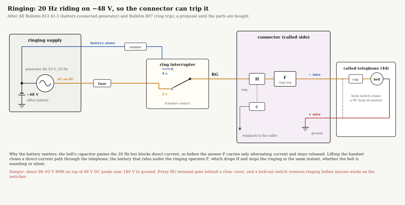
Bulletin 812 says the generator’s output “is usually connected either to negative exchange battery (−48v dc) or to positive exchange battery (ground potential) to facilitate proper operation of ringing power control circuits.” It calls these a battery-connected generator and a ground-connected generator (§3.3.1).
The ringing path figure at the top of this volume shows why the battery connection matters. In the connector, relay H connects the RG lead to the called line through the winding of the ring-trip relay F (Volume 3, step 9). Before the answer, the only path through the telephone is the bell and its capacitor. The capacitor passes the 20 Hz but blocks direct current, so F, which needs direct current, stays released while the bell rings. Lifting the handset closes a direct-current loop through the telephone. The battery under the ringing now flows, F operates, H drops, and the ringing stops at once.
The interrupter therefore must not leave the RG lead dead in the silent part of the cycle. The proposal uses a transfer contact: generator plus battery for the two seconds of ringing, battery alone (through a resistor) for the four seconds of silence. The ring trip then works whether the bell is sounding or silent when the handset lifts.
Record which connection is built, because it changes the Type 26A’s ring-trip test: the false-trip resistance is 2300 Ω for a battery-connected generator, 2200 Ω for superimposed ringing and 2500 Ω for a ground-connected generator (history Volume 8).
4.5.3 Ringback
Ringback is not a separate tone in a step-by-step connector. The connector couples a little of the called line’s ringing back to the caller through capacitors, so the caller hears the ring in step with the bell (history Volume 5). Pure 20 Hz is nearly inaudible in a telephone receiver, so ringing generators were deliberately made non-sinusoidal to give a ringback the caller could hear (Kerr, in history Volume 5).
That matters when choosing a modern generator. A clean sine-wave generator rings the bells well but may give a faint ringback. Bulletin 812 describes the alternative: a separate ringback tone, “420 cycles modulated by 40 cycles”, which “magnetic and transistorized ringing equipment can be provided with” (§4.1). If the ringback is too quiet, a ringback tone switched by the ring interrupter and fed through a capacitor fixes it. Listen first. The connector’s own drawing will show where ringback enters.
4.5.4 Choosing the generator
The sourcing notes found three kinds:
- Current production, battery-referenced or floating. A Cambridge Electronics Labs “Black Magic” sine generator (48 V in, 86 V RMS, 20 Hz, 25 W, floating output that passes DC) or a VIP Ringmaster RP10 (−48 V in, 93 V AC, output referenced to −48 V). Both are quote-only. Either runs straight off the bus.
- Telco surplus. The Charles Industries 8503-00 (−48 V in, 100 V AC, 20 Hz) can be strapped floating, grounded or superimposed on battery, and its optional interrupter gives the 2-on, 4-off cadence built in. It is the most authentic choice and turns up only on the surplus market.
- Hobby modules, 12 V in, 70 V out, about 3 W. Marginal for two old bells.
Whichever is bought, its datasheet must show either a floating output that can be wired in series with the battery, or an output already referenced to −48 V.
4.6 The Interrupters
4.6.1 What they do
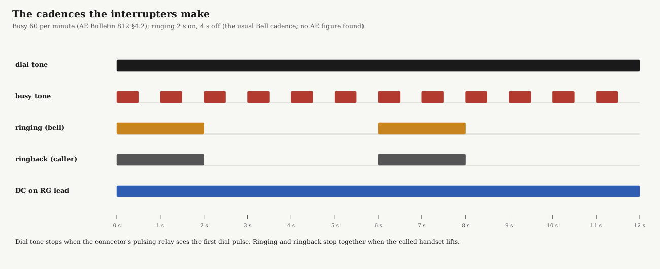
The generators run continuously; the interrupter breaks their output into ringing and silence. In an office it was a motor with “a drive shaft and a number of cams”, each cam working a pile-up of contact springs that controlled interrupter relays (Bulletin 812 §3.3.3). Three more cams cut the busy tone at “30 impulses per minute (ipm) for intertoll-trunks-busy”, “60 ipm for called-line-busy” and “120 ipm for selector (intra-office) all-trunks-busy” (§4.2). This exchange needs two of those cadences: ringing at 2 seconds on, 4 off, and busy at 60 a minute.
4.6.2 Three ways to make the cadence
- Twin timers (the proposal). Two industrial twin timers with independent on and off times, powered straight from the 48 V bus: one set to 2.0 s on and 4.0 s off for ringing, one to 0.5 s and 0.5 s for busy. Each switches its supply through its own changeover contact. They are simple and accurate, and they click audibly.
- A cam interrupter. A motor-driven cam interrupter of the kind Bulletin 812 describes. It is the most authentic, it is fascinating to watch behind a clear cover, and it is found only as surplus.
- Relays alone, the 1944 way. The 10-line PAX of circuit E-75159 made its ringing and its cadence with nothing but relays (figure below).
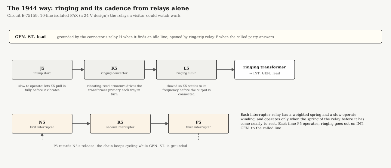
In E-75159, the connector grounds a GEN. ST. lead when it finds an idle line. That starts K5, the ringing converter relay, which “has a vibrating reed armature” and “closes direct current alternately and in opposite direction” to the two halves of the ringing transformer’s primary, so its secondary gives alternating ringing current. J5, the “thump start” relay, is slow to operate so that K5 pulls in fully before its buzzing circuit is closed, and L5 holds off connecting the output until K5 has settled “to its normal vibration frequency.”
The cadence comes from three more relays, N5, R5 and P5. Each has a weighted spring and a slow-operate winding, and each operates only when the weighted spring of the one before it “comes nearly to rest.” The chain keeps cycling while GEN. ST. is grounded, and “each time relay P5 operates, ringing current is connected over the INT. GEN. lead to the called line.” When the called party answers, the ring-trip relay opens GEN. ST. and the whole plant stops.
E-75159 is a 24-volt design, so its relays cannot simply be copied onto a 48-volt panel. The idea transfers, though, and on a display board it beats any timer: a visitor would see the relays rock in the rhythm of the bell. It is noted as a later upgrade.
4.7 Tones
4.7.1 Dial tone and busy tone
Bulletin 812 says tone generators are of the same general types as ringing generators, but use “a lower frequency to modulate a higher frequency”: “the dial and busy tones are 600 cycles, modulated by 120 cycles” (§4.1). The USAF course’s office in history Volume 5 used the same 600 × 120 Hz tone. Busy tone is that same tone interrupted 60 times a minute.
The modern North American “precise tone plan” uses different tones: dial tone is 350 + 440 Hz, busy is 480 + 620 Hz at half a second on and half off, and ringback is 440 + 480 Hz (Wikipedia). For a period exchange the 600 × 120 Hz tone is the authentic one. Since the tones come from recordings, both can be loaded and the choice made by ear.
4.7.2 How the tones get onto the leads
Bulletin 812 is precise about this (§4.3):
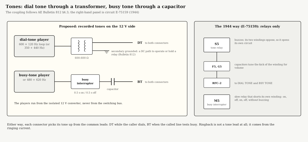
- Each dial-tone lead is connected through “induction coils (transformers) which have their secondaries grounded in order to provide a d-c path for operating or holding a relay.”
- Each busy-tone and ringback lead is connected through “one side of a capacitor”. The capacitor “prevents d-c feedback between different circuits, and helps minimize any crosstalk.”
The proposal follows that exactly. A small audio player loops the dial-tone recording into a 600:600-ohm transformer, with one end of the secondary grounded, and that feeds the DT lead of both connectors. A second player, switched by the busy interrupter, reaches the BT lead through a capacitor. Both players run on the isolated 12-volt side. The transformer and capacitor keep the exchange battery out of the electronics, and the electronics out of the talking path.
E-75159 made its tones with a single relay. S5, the tone generator relay, has two windings that oppose each other, so as soon as it operates it starts to release: “the relay buzzes.” The inductive kick of its winding each time the circuit opens “produces a tone current,” and two capacitors provide “resonance in the circuit to increase the volume.” M5 interrupts the busy tone: a slow relay that short-circuits its own winding, so it operates and releases steadily but “is kept from buzzing.” Like the relay ringing plant, it is a candidate for a later, all-relay version of the board.
A connector picks its tone up from these common leads: dial tone while it waits for the first digit (a P-A-X connector returns its own dial tone, Volume 3), busy tone when the called line tests busy.
4.8 The 12-Volt Side
The LED display, the tone players and any electronic timers run from a separate isolated 12-volt supply: a DC-DC converter fed from the 48-volt bus (its input is isolated from its output) or a small mains supply. Three rules:
- Its return is not the ground bar. The display’s 12 volts is its own circuit. Each LED watches the exchange through an opto-isolator (Volume 5), so no part of it touches + or −.
- No electronics on raw 48 V. Switch magnets and relay coils throw large voltage spikes when they release. Timers and audio modules on the switching bus would see every one of them.
- Tones cross through a transformer or a capacitor, never by a direct connection.
4.9 Safety
- Ringing voltage can hurt. About 86–100 V RMS at 20 Hz on top of −48 V DC peaks at roughly 170–190 V to ground (history Volume 8). Every RG terminal and every bank that carries ringing goes behind a clear cover. Label it RINGING VOLTAGE, fuse the generator separately, and fit a lock-out switch that removes ringing before anyone works on the switches.
- Mains wiring. An open-frame supply has exposed mains terminals. Mount it inside an enclosure in the guarded power section, feed it through a fused and switched inlet, earth its case, and keep mains wiring physically apart from the 48-volt wiring.
- 48 volts is low voltage but high current. A dropped tool across the bus will arc and weld. Every branch is fused, and a main fuse sits between the supply and the panel.
- One ground point. Before tying + to ground, check with the supply unpowered that its output really floats from its case.
4.10 Bringing It Up, in Order
Bring the common equipment up before any switch is connected, one supply at a time, measuring as you go:
- Supply alone. With mains off, check the output floats from the case. Power up with no load, trim to 49.0 V, and check the voltmeter against a multimeter.
- Ground and bus. Connect + to the ground bar. With every fuse out, check −48 V reaches the fuse panel’s bus and nothing else.
- Alarm. Fit a deliberately blown (or flagged) fuse in a spare position: the red lamp lights. Remove it.
- Ringing. Fuse in the generator only. With a true-RMS meter on the RG lead to ground, read the AC (about 86–100 V) and the DC (about −48 V) separately. Ring one telephone directly from RG through a capacitor; its bell should ring loudly.
- Ring cadence. Watch the interrupter for a minute: 2 s on, 4 s off, with the DC still there in the off periods.
- Tones. Listen on a test handset across the DT lead and ground, then on BT: steady dial tone, then busy at one beat a second.
- Then the switches, one fuse at a time, in the wiring order of Volume 3. Watch the ammeter as each switch steps for the first time.
AE’s small P-A-X instructions ask for a monthly test of the charge alarm and a monthly inspection of the battery, charger or battery eliminator (Operating Bulletin 32A1). On a display board, step 1’s voltage check and step 3’s alarm test belong in the same monthly routine.
4.11 In the Reference Library
- AE Training Bulletin 812: Power and Supervisory Equipment: the office power plant, fuses and alarms, ringing generators and interrupters, and tones.
- E-75159 10-Line Isolated PAX: the relay ringing converter, relay interrupter chain and buzzing tone relay (a 24-volt design).
- AE Training Bulletin 818: P-A-X’s: the power equipment of AE’s packaged P-A-Xs.
- Technical Bulletin 565: General Maintenance of P-A-X’s: the P-A-X power panel, ringing converter and tone equipment.
- Operating Bulletin 32A1: installing a small P-A-X’s power supply, and its routine checks.
- Bulletin 1026: Strowger P-A-X: AE’s 1929 P-A-X range, with vibrating ringing converters and trickle-charged batteries.
Sources
- Automatic Electric, Training Bulletin 812: Power and Supervisory Equipment (1960), sections 1–5, Reference Library.
- Automatic Electric, circuit explanation E-75159 (1944), relays J5–T5, Reference Library.
- Automatic Electric, Training Bulletin 818: P-A-X’s with P-A-B-X Appendix (1959), Reference Library.
- Automatic Electric, Technical Bulletin 565: General Maintenance of P-A-X’s (1961), Reference Library.
- Automatic Electric, Operating Bulletin 32A1, maintenance schedule, Reference Library.
- Automatic Electric, Bulletin 1026: Strowger P-A-X (1929), Reference Library.
- Telephone Switching History, Volume 5 (battery, tones, ringing, ringback, Kerr’s cadence) and Volume 8 (bench power, the P.E.I. demonstrator, the Type 26A’s voltage window and ring-trip test, ringing safety), on this site.
- “Precise tone plan”, Wikipedia.
- Equipment figures (Mean Well RSP-500-48 datasheet; Charles Industries 8503-00; Cambridge Electronics Labs NNS; VIP RP10): the sourcing notes behind Volume 2.