My Strowger PBX · Volume 5
Watching a Call
5.1 What This Volume Covers
The exchange already shows a lot by itself. The switches climb and turn under clear covers, the relays click, and the ammeter needle kicks with every magnet. What a visitor cannot see is the state of a call: which relay has operated, whether the line is busy, why the connector stopped where it did. This volume adds lights for that: one LED for each thing worth watching, each placed beside the part it watches.
The idea is not new. Real offices had lamps that showed call states: shelf alarm and supervisory lamps, indicating fuses, and connector supervisory leads that lit a lamp when a party hung up (history Volume 8). The project’s inspiration piece goes further. David Goodsell’s step-by-step demonstrator shows the dialled digits on surplus electromechanical seven-segment displays, driven by his own driver boards under an Arduino Mega, per the Hackster summary of his Nuts & Volts article.
The volume covers:
- The one rule: isolation.
- How one LED watches one relay: two ways.
- The LED map: every light, and the relay or magnet it watches.
- Lights that need two conditions: dial tone, and ringing in time with the bell.
- Showing the digits.
- The display supply, the parts, and a call as the lights show it.
Everything here is a proposal. The exact relay for each light comes from each switch’s circuit drawing, once the switches are bought.
5.2 The Rule: Isolation
Every circuit in the exchange sits at −48 volts, and the ringing lead carries 20 Hz at up to about 100 V RMS on top of that, peaking near 180 volts to ground (Volume 4). The display must never become part of any of that. Three rules follow, and every tap below obeys them:
- The display has its own supply, an isolated 12 V supply whose return is not the exchange’s ground bar (Volume 4, “The 12-Volt Side”).
- Every LED watches a relay or a magnet, never a line. Nothing is connected to the + and − wires, the RG lead or the tone leads. The ringing light watches relay H, which switches the ringing, not the ringing itself.
- The crossing is made by an opto-isolator or by a spare relay contact, so there is no wire between the two sides.
That last rule matters for more than safety. A display wired into the talking path would add noise, and a fault in the display could hold a line or stop a switch releasing.
5.3 How One LED Watches One Relay
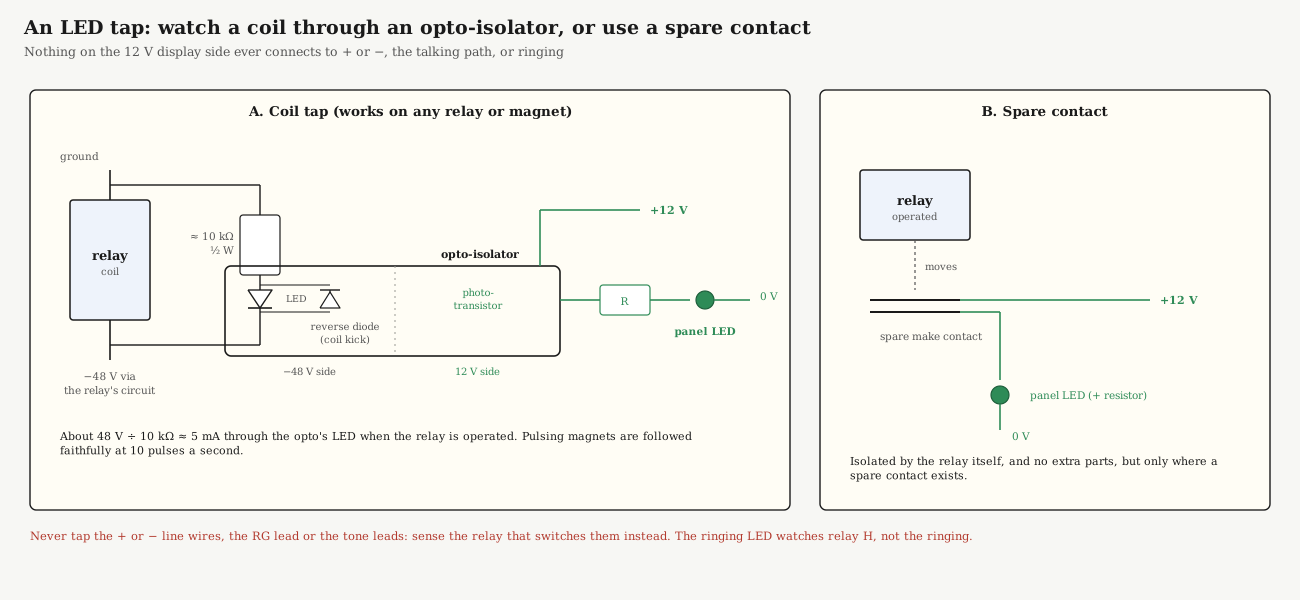
A. The coil tap works on any relay or magnet. When a relay operates, there is about 48 volts across its coil. A resistor and the input LED of an opto-isolator connected across the coil see the same voltage: with about 10 kΩ, roughly 5 mA flows, enough to turn the opto on. A small diode reversed across the opto’s LED takes the voltage spike the coil throws when it releases (Volume 4 warns that relay coils and magnets do this). On the far side of the opto, a phototransistor switches the panel LED from the 12 V display supply. The two sides share nothing but light.
A ½-watt resistor is enough: 48 V across 10 kΩ dissipates about 0.23 W. Magnets that pulse with the dial are followed faithfully: at ten pulses a second, the LED on a vertical magnet flickers once for each pulse.
B. The spare contact needs no extra parts at all. Telephone relays carry several spring pile-ups, insulated from each other. A spare make contact switching the 12 V supply to an LED is already isolated by the relay itself. The catch is that it needs a spare contact, and the relays in the switches were built with the springs their circuits needed. Where a spring can be added, or a relay has one free, use it.
Proposal: coil taps throughout, so that no relay has to be modified, and spare contacts only where a light needs a “not operated” condition (next section but one).
5.4 The LED Map
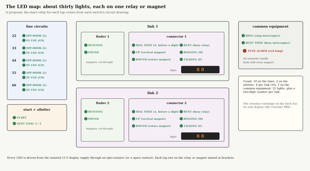
The map at the top of this volume puts each light beside the part it watches. As a table:
Table 1 — The map at the top of this volume puts each light beside the part it watches. As a table
| Where | Light | Watches | Lit when |
|---|---|---|---|
| Each line (22, 33, 44, 55, 66) | OFF-HOOK | line relay L | the handset is lifted and the line is calling |
| IN USE | cut-off relay CO | a finder or connector has taken the line | |
| Start and allotter | START | the start relay | any line is calling and a finder is starting |
| NEXT LINK 1 / 2 | the allotter | which link will take the next call | |
| Each finder | HUNTING | the finder’s vertical and rotary magnets | it is stepping up, then round, looking for the caller |
| FOUND | the finder’s cut-through relay | it has stopped on the calling line | |
| Each connector | DIAL TONE | relay A and the vertical off-normal at normal | the caller hears dial tone and has not dialled yet |
| UP | the vertical magnet | one flash per pulse of the first digit | |
| ROUND | the rotary magnet | one flash per pulse of the second digit | |
| BUSY | the busy relay | the called line tested busy; busy tone is going back | |
| RINGING | relay H and the ring interrupter | flashes in time with the called bell | |
| TALKING | ring-trip relay F | the called party has answered | |
| Common equipment | RING | ring interrupter | the 2-on, 4-off cadence |
| BUSY TONE | busy interrupter | the 60-a-minute cadence | |
| FUSE ALARM (red) | the fuse panel’s alarm contact | any fuse has blown (Volume 4) |
That is 31 lights: 10 on the lines, 2 on the allotter, 8 on each of the two links, and 3 on the common equipment. The Bill of Materials allowed about 40, which leaves room for the phase-2 selectors, whose obvious lights are their own UP, HUNTING (round the level) and ALL BUSY.
The relay letters follow the connector of Volume 3 and the history dive’s Volume 5: A the pulsing relay, H the ringing relay, F ring trip. The finder’s cut-through relay and the connector’s busy relay have different letters in different circuits; the drawing of each switch bought settles them.
5.5 Lights That Need Two Conditions
Two lights would mislead if they watched one relay alone:
- DIAL TONE. Relay A stays operated for the whole call, not only while dial tone is heard. What marks “dial tone, nothing dialled yet” is A operated and the connector’s shaft still at normal. So the DIAL TONE light’s opto transistor is wired in series with a spare break spring of the connector’s vertical off-normal springs, on the 12 V side. The moment the first pulse lifts the shaft, the off-normal springs operate and the light goes out, exactly when the caller’s dial tone stops.
- RINGING. Relay H stays operated through the whole ringing period, rings and silences alike. To flash in step with the bell, the RINGING light’s opto transistor is wired in series with the RING interrupter’s opto transistor, again on the 12 V side. The light then flashes 2 seconds on, 4 off, only on the connector that is ringing.
Putting two opto transistors (or an opto and a spare contact) in series is an AND: both must be on for the LED to light. All of it happens on the isolated 12 V side.
5.6 Showing the Digits
The UP and ROUND lights flash once per pulse, but a visitor counting flashes at ten a second will lose track. A two-digit counter on each link shows the number as it is dialled:
- The counting reads the same opto outputs as the UP and ROUND lights. Each pulse of the vertical magnet adds one to the tens digit, each pulse of the rotary magnet one to the units. When the connector releases (its off-normal springs restore), the counter clears.
- The display is the choice that makes it special. A small microcontroller can drive ordinary LED seven-segment digits. Or, following Goodsell’s demonstrator, it can drive electromechanical seven-segment displays, whose segments flip with a click, matching the rest of the panel.
- A zero is ten pulses. A dialled 0 is ten pulses and puts the shaft on level ten (history Volume 3); the counter shows it as 0.
The microcontroller sits entirely on the 12 V side and only reads opto outputs, so it cannot affect a call. If it crashes, the counters stop and the exchange carries on.
The switch itself is the other digit display. After the second digit, the connector’s wipers are sitting on level 4, contact 4 for 44, and under a clear cover the visitor can count the levels.
5.7 The Display Supply and Parts
- Supply: an isolated 12 V DC-DC converter fed from the 48 V bus, or a small mains supply (Volume 4). Thirty-one LEDs at 10 mA each is about 0.3 A, plus the counters; the 2.5 A converter in the sourcing notes is ample.
- Opto-isolators: one per tap, about 30. Any common single-channel phototransistor opto-isolator, of the 4N25 or PC817 kind, will do. Mount them on small boards beside the relays they watch, so that each tap’s −48 V wiring stays short.
- Per tap, on the −48 V side: a 10 kΩ ½ W resistor and a small reverse diode.
- Per LED, on the 12 V side: a series resistor of about 1 kΩ for roughly 10 mA.
- LEDs: panel-mount, in colours that mean something: green for a line or link in use, amber for stepping, red for busy and the alarm, white for dial tone, blue for talking. Final colours are an aesthetics choice.
- Counters: a microcontroller board and two two-digit displays.
5.8 A Call as the Lights Show It: 22 Calls 44
- 22 lifts the handset: 22 OFF-HOOK and START.
- Finder 1 starts: HUNTING flickers as it climbs one level and turns to contact 1.
- It finds 22: FOUND, 22 IN USE; 22 OFF-HOOK goes out as the cut-off operates.
- Connector 1 returns dial tone: DIAL TONE.
- 22 dials 4: DIAL TONE goes out, UP flashes four times, and the counter shows 4.
- 22 dials 4 again: ROUND flashes four times; the counter shows 44.
- 44 is idle: RINGING flashes in time with 44’s bell; 44 IN USE lights.
- 44 answers: RINGING goes out, TALKING lights.
- Both hang up: every light on link 1 goes out, and the counter clears.
If 44 had been busy, BUSY would light at step 7 instead, alongside the BUSY TONE cadence light.
The crossbar exchange on the back of the panel has its own display, built on the same rules (My Crossbar PBX).
5.9 In the Reference Library
- AE Training Bulletin 807: The Connector: the connector relays the lights watch.
- AE Training Bulletin 821: Linefinder Switches: the line circuit, start and finder.
- AE Training Bulletin 812: Power and Supervisory Equipment: the office’s own alarm and supervisory lamps.
Sources
- Telephone Switching History, Volume 3 (levels and the dialled 0), Volume 5 (connector relays) and Volume 8 (office lamps; isolation), on this site.
- My Strowger PBX, Volume 3 and Volume 4, on this site.
- David Goodsell’s demonstrator: Hackster (summary; the page itself refuses automated reads) and Nuts & Volts.