My Crossbar PBX · Volume 3
Wiring
3.1 What This Volume Covers
Volume 1 laid out the exchange: one 10 × 10 crossbar switch, telephones 61–64 on verticals 1–4, a trunk to the Strowger P-A-X on vertical 9, and three links on bars 1–3, run by the six relay circuits of the 755A plan. This volume shows how those parts are wired together:
- The leads: the wires every part of the exchange uses.
- The switch’s multiples: what goes to each vertical, each row and each crosspoint.
- The circuits: the line circuit, the link, the common control’s sequence, and the trunk.
- Power distribution.
- Two calls followed wire by wire: 61 calls 63, and 62 calls the Strowger panel.
- The order to wire and bring it up.
This is the system wiring, and it is a design proposal. The 755A articles describe what each circuit does (Bell Laboratories Record, June 1938), and the 755A’s General Description practice walks through a call relay by relay, but its main circuit drawings (SD-66504-01, line, line switch and call allotter; SD-66611-01, link and link allotter; SD-66503-01, trunks) have not been found. So the circuits here are designed from that description, from the relays of the Strowger build’s connector, which does most of the same jobs, and from the rules for driving a crossbar switch. The spring-by-spring wiring waits for the switch actually bought: its contact count per crosspoint, its off-normal springs and its magnet coils.
3.2 The Leads
Table 1 — The Leads
| Lead | Runs between | What it carries |
|---|---|---|
| T and R | telephone, line circuit, vertical multiple; link row multiple, link | the talking path, the dial pulses, ringing to the called telephone. T is the + wire, R the − wire of the Strowger build |
| S (hold) | link row multiple → crosspoint → vertical multiple → hold magnet | ground from the link that keeps the vertical’s hold magnet operated for the whole call |
| HM1–HM9 | common control → hold magnet of each vertical | battery to operate a vertical; afterwards S holds it |
| SM1U … SM5D | common control → select magnets | battery to rotate a bar up (U) or down (D); never more than one at a time |
| ON | off-normal springs of each bar and each vertical → common control, line circuit, link | ”this bar is rotated”, “this vertical is in”: the switch reporting back |
| BY1–BY9 | vertical off-normal springs → every link’s busy test | ground while a line is in a call |
| ST, LS1–LS9 | line circuits and the trunk → common control | start, and which line is calling |
| RG, DT, BT | common equipment → every link | ringing, dial tone and busy tone, as on the Strowger panel |
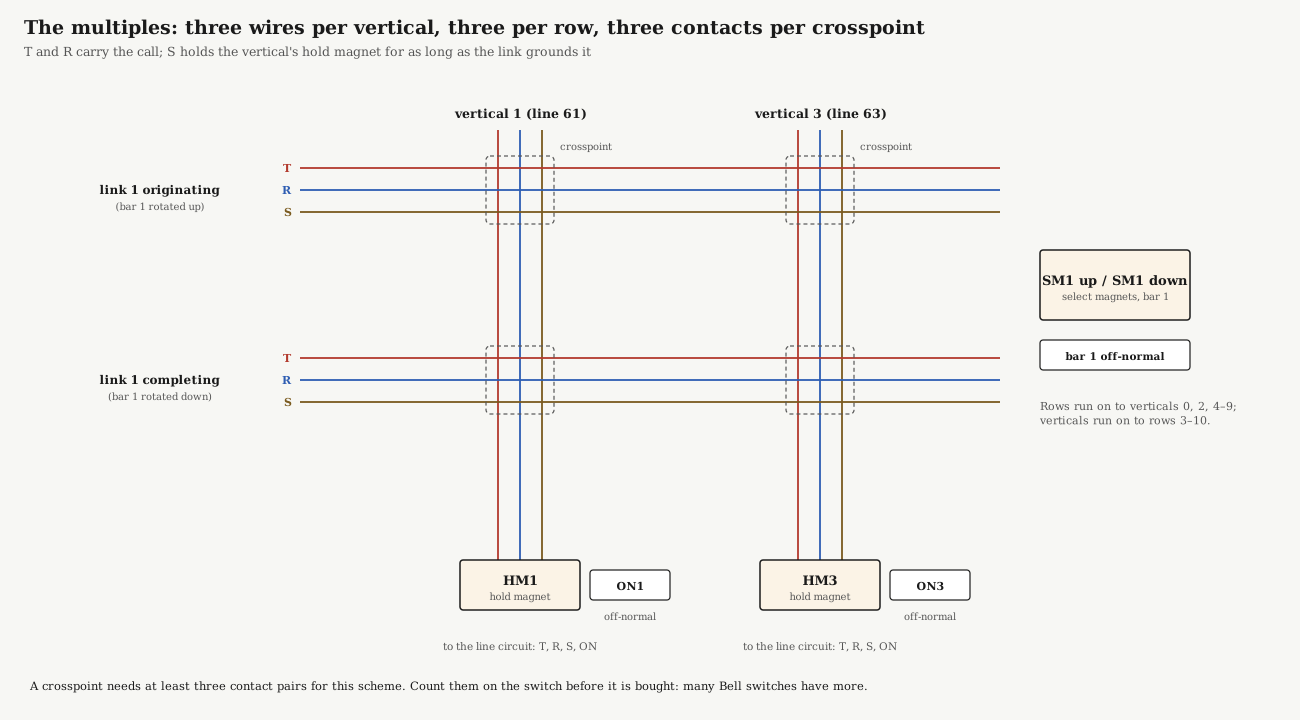
The S lead is the key to holding. The common control operates a hold magnet only for an instant; what keeps it in for the rest of the call is ground from the link, sent over the row’s S wire, through the third contact pair of the crosspoint the magnet has just closed, and down the vertical’s S wire to the magnet. When the link takes the ground away, the magnet releases and the crosspoint opens. A connection holds exactly as long as the link wants it, through its own contacts.
The 755A held its connections the same way, by a slightly different route. In its line circuit, the cut-off relay CO operated the holding magnet and “prepare[d] a locking path for itself through the crosspoints of the crossbar switch”; once the crosspoints closed, CO “locks to ground through two sets of crosspoints, the contacts of the (B) and (A) relays in the link circuit,” so the connection stayed up exactly as long as the link’s A relay held (Bell System Practice 550-550-110, General Description, 755A PBX (1937), §6.08–6.12). Either way, the link’s ground, carried through the crosspoint itself, holds the call. The proposal here puts the hold magnet directly on the S lead; following the 755A’s route instead is a choice for when the relays are designed.
3.3 The Switch’s Multiples
The figure at the top of this volume shows a corner of the switch. Each vertical’s T, R and S run the full height of the switch, past every crosspoint in the column, and each row’s T, R and S run its full width. At every crosspoint, three contact pairs can join the three wires of the vertical to the three wires of the row. This is what Reynolds described in 1937: “One contact of each pair is multipled with the corresponding contacts of the other pairs in the same column, and the other contact of each pair is multipled with the corresponding contacts of the other pairs in the same row” (Bell Laboratories Record, July 1937).
Table 2 — The Switch's Multiples
| Switch position | Wired to |
|---|---|
| Vertical 0 | spare |
| Verticals 1–4 | telephones 61–64, through their line circuits |
| Verticals 5–8 | spare |
| Vertical 9 | the trunk circuit, to line 66 of the Strowger P-A-X |
| Bar 1 up / down rows | link 1 originating / completing |
| Bar 2 up / down rows | link 2 originating / completing |
| Bar 3 up / down rows | link 3 originating / completing |
| Bars 4 and 5 | spare: room for links 4 and 5 |
Check before buying: this scheme needs at least three contact pairs at every crosspoint. Many Bell switches have more, and spare pairs can light the display.
3.4 The Line Circuit
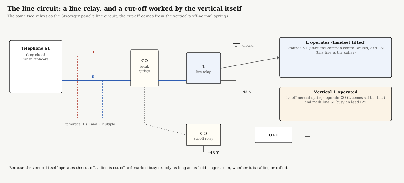
The line circuit has the same two relays as the Strowger panel’s (My Strowger PBX, Volume 3), with one change that the crossbar switch makes possible. The line relay L is bridged across the line through break springs of the cut-off relay CO. Lifting the handset operates L, which grounds ST (the common control wakes up) and LS1, which tells the common control that it is line 61 calling.
The cut-off relay is operated by the vertical itself. The 755A used each bar’s and vertical’s off-normal contacts “for a variety of purposes such as indicating whether or not a bar is operated” (Reynolds, 1938). Here vertical 1’s off-normal springs operate CO, which takes L off the line, and also ground BY1, which marks 61 busy for every link’s busy test. A line is therefore cut off and marked busy exactly as long as its vertical is held, whether it made the call or received it.
3.5 The Link
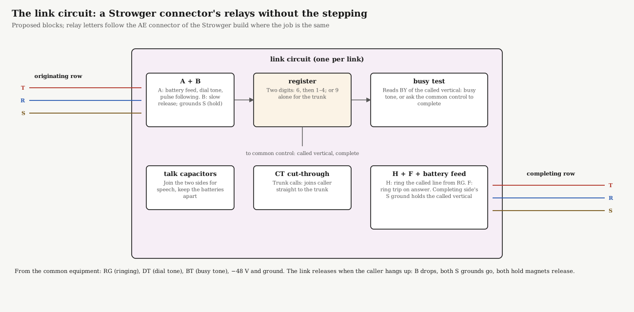
A link does nearly everything a Strowger connector does, except step: the crossbar switch has already put it on the caller’s line, and will put it on the called line when told. Gray’s description of the 755A’s link sets its jobs: “Dial tone is received through the link by the calling station, which then dials. Pulsing and register relays in the link circuit record the two digits dialed, and at the completion of dialing the link tests the called line and returns a busy signal if it is busy.”
Table 3 — The Link
| Block | Relays (proposed) | Job |
|---|---|---|
| A | 1 | Across the originating T and R: feeds battery to the caller, connects DT for dial tone, follows the dial pulses |
| B | 1, slow to release | Holds through the pulses; while operated, grounds the originating row’s S, holding the caller’s vertical |
| Register | relay counting chains or a stepping switch per digit (Volume 2) | Records 6 then 1–4, or 9 alone; outputs the called vertical’s number |
| Busy test | 1 | Reads BY of the called vertical: ground means busy, so BT goes to the caller; otherwise asks the common control to complete |
| H, F | 2 | H connects RG to the called line through ring-trip relay F; F operates on answer and stops the ringing, as in a Strowger connector |
| Completing feed and hold | 1–2 | Feeds battery to the called party; grounds the completing row’s S, holding the called vertical |
| Talk capacitors | — | Join the two sides for speech while keeping their battery feeds apart |
| CT | 1 | Cut-through for trunk calls: joins originating T and R straight to the completing side, and takes A and the feeds off |
Release. The link releases when the caller hangs up. A drops, B releases after its slow-release time, both S grounds go, both hold magnets release, and both crosspoints open. The verticals’ off-normal springs restore the two line circuits.
3.6 The Common Control
How the 755A did it. The 755A’s line circuit had a line relay L and a marginal relay L1 that operated in series with the start relay ST of an idle link. Four call allotter relays (S, E, MS and E1) let only one line at a time reach the select magnets: if two lines called together, “only the (L1) relay of line 20 (lower numbered line) would lock,” and the other waited. A link allotter of three relays (CH1–CH3) chose the link, rotating “successive links on successive calls” so traffic spread evenly. When all links were busy, the caller’s line operated a busy relay BY and heard busy tone at once (Bell System Practice 550-550-110, General Description, 755A PBX (1937), §3.02, §6.06–6.14). The common control proposed below does the same jobs.
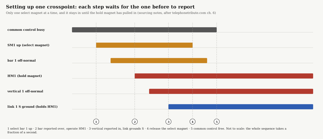
The common control is the only circuit that touches the select and hold magnets, and it uses the switch’s own off-normal springs to know that each step has happened before taking the next. That follows the rules for driving a crossbar switch: only one select magnet operates at a time, and it must stay operated until the hold magnet has pulled in (sourcing notes, after telephonetribute.com). Then the select magnet releases, and “all the fingers return with it except the one held by the holding bar” (Reynolds, 1937).
It does two jobs:
- Connect a caller. ST and LS say which line is calling. The link allotter names an idle link. The common control operates that link’s bar up, then the caller’s hold magnet, waits for the link’s S ground to take over, releases the bar, and goes back to normal.
- Complete a call. A link that has a number and an idle line asks for completion. The common control operates that link’s bar down, then the called line’s hold magnet, waits for the completing S ground, releases the bar.
Each job takes a fraction of a second, so one common control serves every link, as in the 755A: “If it is in use on one call when needed on another, the delay while waiting for it to become idle is only a fraction of a second and is unnoticeable.”
3.7 The Trunk to the Strowger System
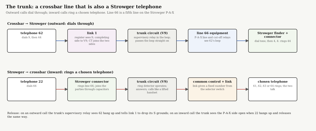
To the Strowger P-A-X, the trunk is line 66: a fifth line, with its own line and cut-off relays and its own place on the finder and connector banks (Volume 2, items 5.2–5.3). To the crossbar exchange, it is vertical 9, a line like any other.
- Outward (crossbar to Strowger). The register recognises 9 as a complete number. The common control connects the link’s completing side to vertical 9, and the link operates CT, so the caller’s loop runs straight through the link and through the trunk circuit’s supervisory relay to line 66. The P-A-X sees a telephone lifted: its line relay operates, a finder finds line 66, a connector returns dial tone, and the caller dials 22, 33, 44 or 55 directly. When the caller hangs up, the supervisory relay releases and tells the link to drop its S grounds.
- Inward (Strowger to crossbar). A Strowger telephone dials 66, and the Strowger connector rings the trunk. The trunk circuit’s ring detector operates; the trunk answers, which trips the Strowger ringing, and calls the crossbar common control like a lifted handset. Its link is given a fixed number from a selector switch on the panel (61, 62, 63 or 64), tests that line and rings it. The Strowger caller cannot dial the crossbar number instead: the Strowger connector joins the two parties through capacitors (history Volume 5), and dial pulses, which are breaks in direct current, do not pass.
3.8 Power Distribution
The same rules as the Strowger panel (My Strowger PBX, Volume 4): −48 V with the positive side grounded at one point, a fuse per load, ringing on battery, and the display on its own isolated supply. Proposed fuses:
Table 4 — The same rules as the Strowger panel ([My Strowger PBX, Volume 4](https://telephones.fubsypoly.com/my-strowger-pbx/vol-4/)): −48 V with the positive side grounded at one point, a fuse per load, ringing on battery, and the display on its own isolated supply. Proposed fuses
| Fuse | Load |
|---|---|
| X1 | select magnets (SM1U–SM5D) |
| X2 | hold magnets (HM0–HM9) |
| X3 | line circuits and trunk circuit |
| X4–X6 | links 1–3 |
| X7 | common control and link allotter |
| X8 | ringing to the links’ RG (if the crossbar system has its own ringing) |
Hold magnets are a steady load. A Strowger magnet draws current only while it steps; a crossbar hold magnet draws for the whole call (sourcing notes, after US 3,400,225). Two calls in progress hold four verticals in. Measure one hold magnet’s current on the switch bought, multiply by four, and add it to the supply’s steady load before sharing the Strowger supply.
3.9 A Call Wire by Wire: 61 Calls 63
- 61 lifts the handset. The loop through the telephone operates L on line 61, through CO’s break springs. L grounds ST and LS1.
- A link is chosen. The link allotter names link 1. The common control operates SM1U: bar 1 rotates up, and every finger on it lies behind the originating row’s contacts.
- The caller’s crosspoint closes. Bar 1’s off-normal springs report it rotated. The common control operates HM1; vertical 1’s holding bar presses the finger at link 1 originating, and the three contact pairs close: 61’s T, R and S now reach link 1.
- The hold passes to the link. Link 1 has been started; its A relay, across 61’s loop through the crosspoint, operates, and B grounds the originating S. That ground runs through the closed crosspoint to HM1 and holds it. Vertical 1’s off-normal springs operate CO on line 61 (L comes off) and ground BY1 (61 is busy).
- The bar returns. The common control releases SM1U. Bar 1 swings back to the middle; every finger goes with it except the one trapped by vertical 1. The common control is free.
- Dial tone and dialling. A connects DT, and 61 hears dial tone. 61 dials 6 and 3; A follows the pulses, and the register records them. Nothing on the switch moves.
- Busy test. The register names vertical 3. The busy test looks at BY3: no ground, so 63 is idle.
- The called crosspoint closes. Link 1 asks the common control to complete. It operates SM1D: bar 1 rotates down. Then HM3: vertical 3’s holding bar closes the crosspoint at link 1 completing. Link 1 grounds the completing S, which holds HM3; vertical 3’s off-normal springs cut off 63’s line relay and ground BY3. SM1D releases and bar 1 returns, now holding two fingers.
- Ringing. H connects RG through F to 63’s line. 63’s bell rings; ringback reaches 61 through the link’s capacitors.
- Answer. 63 lifts the handset; direct current flows through F, which operates and drops H. Ringing stops; battery feeds both sides; 61 and 63 talk through the capacitors.
- Release. 61 hangs up. A drops; B releases after its delay; both S grounds go. HM1 and HM3 release, both crosspoints open, and the off-normal springs restore both line circuits. (If 63 hangs up first, the link waits for 61 to hang up before releasing.)
3.10 A Call to the Strowger Panel: 62 Dials 9, Then 44
- Steps 1–6 as above, for line 62 on vertical 2 and link 2.
- 62 dials 9. The register recognises a complete number and names vertical 9. BY9 is clear, so the trunk is free.
- The common control rotates bar 2 down and operates HM9. Link 2 grounds the completing S and operates CT: 62’s T and R now run through link 2, vertical 9 and the trunk’s supervisory relay to line 66 of the P-A-X.
- On the Strowger panel, line 66’s line relay operates. A finder hunts and finds line 66, its connector returns dial tone, and 62 hears it.
- 62 dials 4, 4. The pulses travel as breaks in 62’s own loop, straight through the crossbar switch, to the Strowger connector, which steps up four and round four and rings 44.
- 44 answers through the Strowger connector. When 62 hangs up, the P-A-X releases as usual, and the trunk’s supervisory relay tells link 2 to drop its S grounds: HM2 and HM9 release.
A visitor sees both kinds of switching in one call: the crossbar’s bar rocking and verticals snapping in, then the Strowger finder and connector climbing and turning.
3.11 Wiring It Up, in Order
- The switch alone. Mount it, terminate its multiples and magnet leads, and bring it up with the microcontroller rig (Volume 2, item 9.1): operate each select magnet and each hold magnet, and check every crosspoint’s three contact pairs close and open, and every off-normal spring reports.
- Power and fuses.
- Line circuits 61–64, tested with a telephone: L operates on lift-off; operating a vertical by hand from the rig operates CO and grounds BY.
- The common control and link allotter, with the rig standing in for a link: a lifted handset should rock a bar up and close the caller’s crosspoint, and nothing else.
- Link 1, without its register at first: dial tone through the switch.
- The register, then the busy test and completion: the first full call, 61 to 63.
- Links 2 and 3: two calls at once.
- The trunk, after line 66 is added to the Strowger panel: outward, then inward.
- The display, last, as on the Strowger panel.
3.12 In the Reference Library
- BSP 550-550-110: 755A PBX, General Description: the 755A’s switch, circuits and a call relay by relay.
- SD-66507-01: No. 755A Station Circuit and the 756A circuit description binder.
- Bell Laboratories Record, June 1938: the 755 PBX’s switch, links and six circuits.
- Bell Laboratories Record, July 1937: the switch’s contacts, fingers and magnets.
- Bell Laboratories Record, January 1959: the 756A, with all circuits on the verticals.
- BSP 551-144-210: tie trunks on a real small crossbar PBX.
- BSP 551-100-100: how a 756A is installed and tested.
Sources
- Bell System Practice 550-550-110, General Description, 755A PBX, issue 1 (1937), Reference Library.
- J. N. Reynolds, “The Crossbar Switch”, Bell Laboratories Record, July 1937, Reference Library.
- J. N. Reynolds, “The Crossbar Switch in the 755 PBX”, and C. R. Gray, “The 755 PBX”, Bell Laboratories Record, June 1938, Reference Library.
- R. D. Williams, “Crossbar Circuitry for a Small PBX”, Bell Laboratories Record, January 1959, Reference Library.
- Driving rules and hold-magnet current: the sourcing notes, citing telephonetribute.com and US 3,400,225.
- Connector relays, ring trip and the capacitor bridge: My Strowger PBX, Volume 3, and Telephone Switching History, Volume 5, on this site.