My Crossbar PBX · Volume 1
The Crossbar Switch and the 755 Plan
1.1 What This Dive Covers
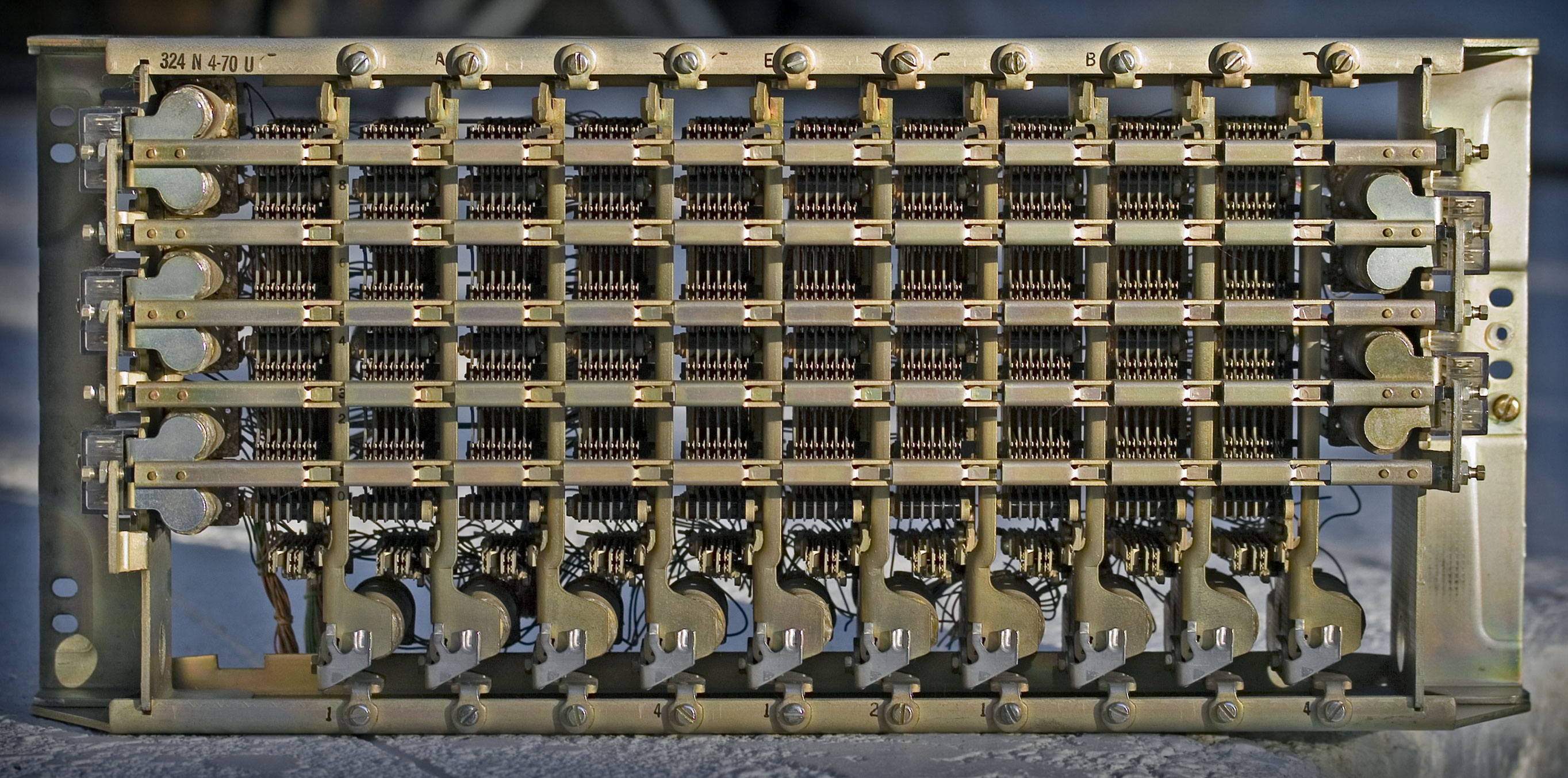
My Strowger PBX is a four-telephone step-by-step exchange on a rolling panel. A visitor lifts a handset and watches the switches climb and turn. This dive plans its companion: a small exchange built around a crossbar switch, the technology that followed step-by-step. Here the switching is done not by wipers sliding over banks but by bars that rock a few degrees and press contacts together.
The two systems should eventually be able to call each other, so a Strowger telephone can ring a crossbar telephone and the other way round.
Nothing is bought or built yet, and no crossbar equipment is in the collection. This first volume sets out how a crossbar switch works, the small Bell System exchange that the build is modelled on, and the proposed system. Everything about the build is a proposal until the hardware is in hand.
1.2 From Brushes to Crosspoints
In 1937 J. N. Reynolds of Bell Telephone Laboratories introduced the crossbar switch by comparing it with what came before (Bell Laboratories Record, July 1937). The manual switchboard connected circuits with a plug and a jack. Step-by-step and panel switching kept the same idea but mechanised it: the jacks became banks of terminals and the plugs became brushes that slid over them. In a step-by-step switch, one brush steps up row by row and then across, one magnet operation per step.
Reynolds saw two weaknesses in this. The brushes needed “a comparatively complex mechanism”, and the contact slid, so it had to be made of hard, durable metal, which “do[es] not have as low contact resistance as the softer precious metals such as silver.”
The crossbar switch removed the brush altogether. Instead of one moving contact searching a bank, it puts a pair of contacts at every position. One contact of each pair is multipled with the others in its column, and the other with the others in its row. To connect a column to a row, “it is necessary only to close the contacts at the proper position”. Nothing slides; the contacts “are merely pressed together as in a relay”. That made precious-metal twin contacts practical, giving “greatly increased assurance that a good connection will be made.”
1.3 How the Switch Closes a Crosspoint
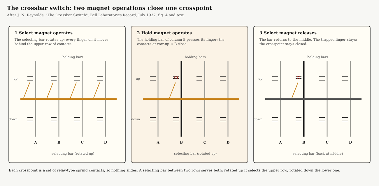
Reynolds’s description of the mechanism is short, and it is the whole secret of crossbar switching:
- Selecting bars run horizontally, one between each pair of contact rows. Each bar can rotate “a small amount in either direction around its axis by the action of two magnets”. Springy wires called selecting fingers stick out from the bar, one at each column. Rotate the bar one way and every finger moves behind the contacts in the row above; rotate it the other way and they move behind the row below.
- Holding bars run vertically, one per column, each worked by its own magnet. When a holding bar operates, it presses against every finger in its column. If no selecting bar has moved, the fingers “will merely be pushed down between the rows of contacts and no connection is made.”
- One crosspoint closes where the two meet. If a selecting bar has been rotated, its finger in that column is lying across the back of a contact spring, and the holding bar pushes it home.
- Then the selecting bar lets go. “The holding bar remains operated during the period of the call, but the selecting bar returns to normal immediately after the holding bar has operated.” Every finger springs back except the one trapped by the holding bar, “thus leaving the selecting bar free for another selection.”
The result is a connection made by two magnet operations, one immediately following the other, where a step-by-step switch needs one operation for every row and every contact it passes. The switch Reynolds illustrated had five selecting bars, and so ten rows, and twenty holding bars. Each crosspoint “represents several contacts”, enough to switch both wires of a talking pair and a control lead at once.
1.4 The 755 PBX: A Whole Exchange on One Switch
The 755A’s own Bell System Practice adds the details of the switch: ten verticals, each with ten sets of contacts “with six pairs of make contact springs in each set,” and five selecting bars with ten selecting fingers each, “a flexible wire about 3 inches long” (Bell System Practice 550-550-110, General Description, 755A PBX (1937)). A year after Reynolds’s article, the Record showed the crossbar switch at work in the 755A PBX, a dial PBX “for residences and smaller business houses” with up to four trunks and twenty station lines (Bell Laboratories Record, June 1938: J. N. Reynolds, “The Crossbar Switch in the 755 PBX”, and C. R. Gray, “The 755 PBX”). It is the model for this build, because a single crossbar switch is the whole of its switching network.
Links, originating and completing. Reynolds starts from the general problem. Every extension can call or be called, so each one is wired to two sets of terminals, one for outgoing and one for incoming calls. A link joins them. The link is “divided by the equipment into two sections: an originating section, which connects to the calling extensions, and a completing section, which connects to the called extension.” His example diagram has “only four extensions … and two links”. A manual board does this with cords and jacks; a step-by-step PBX does it with switches whose brushes move over fixed terminals.
One switch, ten by ten. In the 755A switch the ten verticals are the extension lines. Of the ten horizontal rows, “the upper six horizontal rows serve as trunks for the originating and completing ends of three link circuits, and the lower four rows are for trunks” to the central office. Each horizontal bar has two magnets, “one to rotate the bar in each direction”, so one bar serves both ends of a link: up for the originating end, down for the completing end. Two switches could be combined to give twenty lines.
A local call, in Reynolds’s words. When a line places a call, “the horizontal bar of an idle link is rotated up and immediately afterward the vertical bar corresponding to [the line] is operated, which connects the calling line to the originating side of the link.” The bar returns, but the vertical stays. After the caller dials, “the same horizontal bar is again operated, but this time in the downward, or completing, position,” and the vertical of the line called operates. The bar returns again, “but two of its fingers will remain held: one by the vertical bar of the calling line and one by that of the line called, thus establishing the connection.”
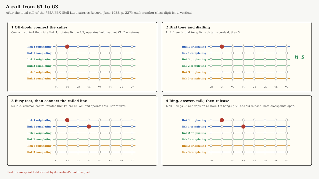
Six control circuits. Gray describes the relays around the switch: “the line circuit; the trunk circuit; the link circuit; the common control and cut-off circuit; the common timing, tone, and ringing circuit; and the ‘link-allotter’ circuit.” There is a line circuit per line and a trunk circuit per trunk, one to three links, and one of each common circuit. In a local call, the line circuit signals the common control, which “determines from the link allotter circuit that an idle link is available”, operates the link’s originating magnet and then the calling line’s holding magnet, and releases. “Dial tone is received through the link by the calling station, which then dials. Pulsing and register relays in the link circuit record the two digits dialed,” and the link tests the called line, returning busy if it is busy. If it is idle, the common control operates the link’s completing magnet and the called line’s hold magnet. “The link then rings on the called line, and when the station answers provides a talking path between the two stations.” The common control is held “only for a very short period at a time,” so it can serve two calls at once with no noticeable delay.
Trunk calls need only one operation: the trunk’s selecting magnet, then the calling line’s hold magnet, and the station is “connected directly to the trunk” and hears the central office’s dial tone. The 755A used special handsets with key buttons: one for local calls, one for holding, and one per trunk. Gray notes that “the usual types of telephone sets may be used in place of the combined handset”, with the buttons fitted elsewhere.
1.5 After the 755: the 756A
The 755A’s successor shows where crossbar PBXs went next (Bell Laboratories Record, December 1957). The 756A of 1957 served 40 or 60 lines with six central-office trunks, using crossbar switches and wire-spring relays in “two modular cabinets” the size of office filing cabinets. Its power supply turned 115 V mains into 48 volts DC, with “a large capacitor” to ride through momentary interruptions and an optional battery cabinet. “Ringing current, signaling tones, and flashing interruptions” came from the same power unit.
The 756A worked “essentially as a small crossbar office”. Registers gave dial tone and received the digits; a marker checked whether the called line was busy, hunted for idle lines and trunks, and set up the connection. Extensions had two-digit numbers beginning 2 to 7; 0 called the attendant; and “dialing an initial 9 causes connection to an idle central-office trunk and the calling station line receives a second dial tone from the central office.” Its circuitry is described in a later Record article (January 1959), and four Bell System Practices in the Reference Library cover its installation, repair and options.
The 756A is far better documented than the 755A, but it is the wrong model for a four-telephone display: it is two cabinets of equipment, and its marker hides the logic. The 755A’s plan, one switch with relay circuits a visitor can follow, is the right size.
1.6 The Proposed Exchange
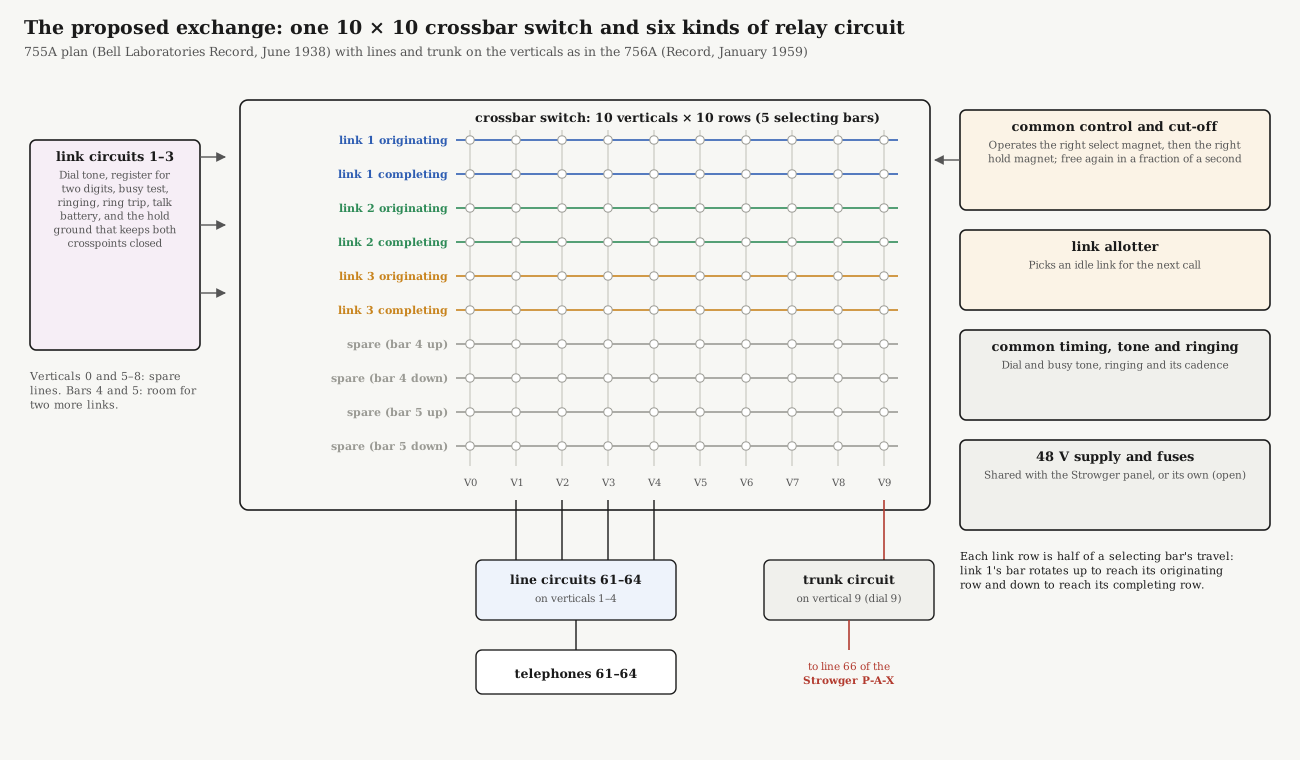
The proposal follows the 755A as closely as a four-telephone exchange allows:
- The switch. One crossbar switch with ten verticals and five selecting bars (ten rows). A Western Electric switch of this size is about 21 × 9 in and about 30 lb (calling315.com; figures from the sourcing notes). An Ericsson switch would also do; the logic is the same.
- Everything on the verticals. The 755A put its trunks on horizontal rows, reached with a key on the telephone. The later 756A wired “all of the communication circuits that can be connected through the PBX … to the verticals”, so any of them can be joined to any other by a link (Bell Laboratories Record, January 1959). This build does the same: telephones 61–64 on verticals 1–4, so each number’s last digit is its vertical, and the trunk to the Strowger P-A-X on vertical 9, the digit dialled to reach it. Verticals 0 and 5–8 are spare.
- Links. The 755A had one to three. Two links let two calls run at once, matching the Strowger panel; a third costs one more link circuit and shows the link allotter choosing between three.
- Rows. Three links use bars 1–3; bars 4 and 5 are spare for two more links.
- The relay circuits are the 755A’s six: line, link, trunk, common control and cut-off, link allotter, and common timing, tone and ringing. Their detailed design waits for the switch, because its magnets set the coil voltages and currents.
- Placement and power. The exchange goes on the back of the Strowger panel, where it is small enough to leave room beside it for text and photographs, and it shares that panel’s 48 V supply, ringing and tones (Volume 4). Check the magnet voltage on the switch bought. The 755A itself ran from a small storage battery giving “a voltage range of 18 to 25 volts” (Bell System Practice 550-550-110, General Description, 755A PBX (1937)), while the 756A ran on 48 V. A switch from a 755A may have 24-volt magnets, one from a later office 48-volt magnets.
- Ordinary dial telephones. The 755A’s key-button handsets are not needed: local calls use the links, and the trunk is reached by dialling, as on the 756A.
Numbering. Two-digit numbers, as the 755A’s link registers recorded, chosen so they never clash with the Strowger panel’s 22, 33, 44 and 55: 61, 62, 63 and 64, with 9 proposed for the trunk to the Strowger system, as on the 756A.
1.7 Calling the Strowger P-A-X
The period way to join two exchanges like these is a trunk. To the Strowger P-A-X, the crossbar’s trunk circuit is simply one more telephone line. It needs a line circuit and a number on the P-A-X, a fifth line beside 22–55 (Volume 3 of My Strowger PBX leaves the rest of the connector bank free).
- Crossbar to Strowger. A crossbar telephone dials 9. The link’s completing side connects to vertical 9 and the link cuts through, so the caller’s loop runs straight to the trunk circuit, which closes it to the P-A-X. The caller hears the Strowger dial tone, the “second dial tone” of the 756A, then dials 22, 33, 44 or 55, and the pulses pass straight through to the Strowger connector.
- Strowger to crossbar. A Strowger telephone dials the trunk’s P-A-X number, 66, and the P-A-X rings the trunk. On the 755A an attendant answered such calls with a key and transferred them. Here the trunk circuit detects the ringing, answers, and calls for a link as if it had dialled a fixed number, so the link rings one chosen crossbar telephone, set by a selector switch on the panel. The Strowger caller cannot dial on to 61–64 directly: once the P-A-X connector answers, it joins the two parties through capacitors (history Volume 5), and dial pulses, which are interruptions of direct current, do not pass. Volume 3 draws both directions.
The 756A’s tie-trunk practice is in the Reference Library (BSP 551-144-210) for when the trunk circuit is designed.
1.8 What a Visitor Sees
On a step-by-step switch the wipers travel. On a crossbar switch almost nothing travels, which is exactly what makes it worth watching up close:
- Lift a handset and a horizontal bar rocks up, a vertical snaps in, and the bar drops back. One crosspoint is now held, and dial tone comes from the link.
- Dial, and nothing moves on the switch at all. The digits go into the link’s register relays.
- The called line is idle, so the same bar rocks the other way, a second vertical snaps in, and the bar drops back. Two fingers are now trapped in one row: that is the call.
- Hang up, and the two verticals let go.
Behind a clear cover, with an LED at each held crosspoint and on each link and register, the switch becomes a map of every call in progress.
1.9 Choosing the Hardware
The sourcing notes (02-inputs/research/crossbar_options.md) compared three routes:
Table 1 — The sourcing notes (02-inputs/research/crossbaroptions.md) compared three routes
| Route | What | For | Against |
|---|---|---|---|
| A. Restore a real small crossbar PBX | Find a 755A or 756A and bring it up | Fully authentic, with its own drawings | None found for sale; a 756A is 40–60 lines in two cabinets, and it hides the mechanism |
| B. One switch, 755A-style relay control (proposed) | One 10 × 10 switch plus relay line, link, trunk and common circuits | Right size; every action visible; period-correct logic | The relay circuits must be designed, from the 755A description and the drawings of what is bought |
| C. One switch, microcontroller control | The same switch, driven from a microcontroller | Quickest way to prove a bought switch works | Hides the logic in software; less to watch |
A sensible order is C first, then B: prove the switch’s magnets and contacts with a simple controller, then replace the controller with relays one circuit at a time. A hobbyist demonstration of an Ericsson crossbar switch with an Arduino in place of its control relays shows route C works (Hackaday, February 2024, from the sourcing notes).
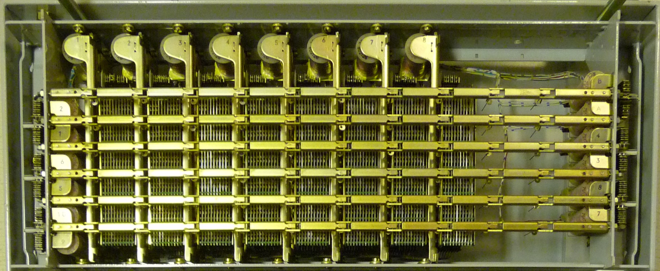
When a switch turns up, the things to check are: that it is complete, with all its bars, fingers and magnets; the coil markings or resistances; any maker’s code on the frame, to find its drawing; and the contact sets at a few crosspoints.
1.10 Open Questions
- The switch. No working crossbar switch was confirmed for sale when the sourcing notes were written (26 October 2026). Collector sold listings and forums are the places to watch.
- Coil voltage and resistance of the switch actually bought.
- The 755A’s circuit drawings. Its General Description practice and station-circuit drawing (SD-66507-01) have been found; the main drawings (SD-66504-01, SD-66611-01, SD-66503-01) have not.
1.11 What Comes Next
The volumes follow the Strowger build’s order: choose the hardware → block diagram → bill of materials → wiring → troubleshooting.
- Volume 2, Bill of Materials: the switch, relays, power, ringing and tones, telephones, the trunk to the P-A-X.
- Volume 3, Wiring: the switch’s leads, the line, link and trunk circuits.
- Volume 4, Power and Control: magnets, timing, tones and ringing.
- Volume 5, Watching a Call: the LED display.
- Volume 6, Troubleshooting.
- Volume 7, My Build.
1.12 In the Reference Library
- Bell Laboratories Record, July 1937: Reynolds, “The Crossbar Switch”: how the bars, fingers and magnets work.
- Bell Laboratories Record, June 1938: the 755 PBX, the model for this build.
- Bell Laboratories Record, December 1957 and January 1959: the 756A and its circuitry.
- 756A Bell System Practices: Installation and Test, Repair, Service Options, Miscellaneous Equipment (tie trunks).
- Crossbar Systems, Peter Walker: a clear introduction, including Ericsson and interworking with Strowger.
- Telephone Communications Systems, Vol. 2: Western Electric’s training text.
- Bell Laboratories Record, March 1949: the No. 5 Crossbar office, for scale.
Sources
- Bell System Practice 550-550-110, General Description, 755A PBX, issue 1 (1937), Reference Library.
- J. N. Reynolds, “The Crossbar Switch”, Bell Laboratories Record, July 1937, pp. 338–343, Reference Library.
- J. N. Reynolds, “The Crossbar Switch in the 755 PBX”, and C. R. Gray, “The 755 PBX”, Bell Laboratories Record, June 1938, pp. 332–340, Reference Library.
- O. H. Williford, “A Modern Crossbar PBX”, Bell Laboratories Record, December 1957, Reference Library.
- R. D. Williams, “Crossbar Circuitry for a Small PBX”, Bell Laboratories Record, January 1959, Reference Library.
- Switch size and weight: calling315.com, via the sourcing notes; not yet checked against a switch in hand.
- My Strowger PBX, Volume 1 and Volume 3, on this site.