My Crossbar PBX · Volume 5
Watching a Call
5.1 What This Volume Covers
On a Strowger switch the wipers travel, and a visitor can follow them. On a crossbar switch a call is set up by a bar rocking a few degrees and a vertical snapping in, and then nothing moves at all: the connection sits in two closed crosspoints among a hundred identical ones. The display’s job on this side of the panel is to show which crosspoints are held, and what each link is doing.
The rules are the same as the Strowger panel’s (My Strowger PBX, Volume 5): the display runs on the shared isolated 12 V supply, every light watches a relay, magnet or spare contact, and nothing touches a line wire, the ringing lead or a tone lead.
5.2 The Crosspoint Mimic
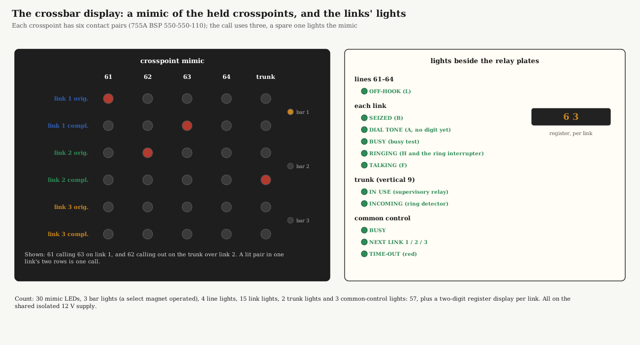
The crossbar switch offers something no Strowger switch can: a spare contact at every crosspoint. Each set of contacts on the 755A’s switch had “six pairs of make contact springs” (BSP 550-550-110), and the call needs only three (T, R and S, Volume 3). A fourth pair, wired to an LED in a grid on the panel, closes exactly when its crosspoint closes.
The result is a mimic of the switch: five columns (61, 62, 63, 64 and the trunk on vertical 9) by six rows (the originating and completing ends of links 1–3), 30 LEDs. A call shows as two lit LEDs in one link’s pair of rows: the caller in the originating row, the called line in the completing row. A call to the Strowger side shows as the caller and the trunk column. Two calls at once are two such pairs.
The spare contact pairs are dry contacts: they are part of the switch, insulated from the talking pairs, and they switch the 12 V display supply directly, with a resistor for each LED. No opto-isolator is needed. Whether a fourth pair is free depends on the switch bought: count the pairs at a crosspoint before relying on them, and if none is free, an opto-isolator on each vertical’s hold magnet (as in the Strowger display) still shows which lines are held, though not which row.
Beside the mimic, a light for each bar shows its select magnet operated: the brief flash, a fraction of a second, when a bar rocks to set up a crosspoint.
5.3 The Lights Beside the Relay Plates
Table 1 — The Lights Beside the Relay Plates
| Where | Light | Watches | Lit when |
|---|---|---|---|
| Each line (61–64) | OFF-HOOK | line relay L | the handset is lifted and the line is calling |
| Each link | SEIZED | relay B | the link has been given a caller |
| DIAL TONE | relay A and the register at zero | the caller hears dial tone and has not dialled | |
| register display | the register | the two digits as they are dialled | |
| BUSY | the busy-test relay | the called line tested busy | |
| RINGING | relay H and the ring interrupter | flashes with the called bell | |
| TALKING | ring-trip relay F | the called party has answered | |
| Trunk (vertical 9) | IN USE | the supervisory relay | a call is on the trunk |
| INCOMING | the ring detector | the Strowger side is ringing the trunk | |
| Common control | BUSY | its sequence relays | it is setting up a crosspoint |
| NEXT LINK 1 / 2 / 3 | the link allotter | which link takes the next call | |
| TIME-OUT (red) | the time-out relay | a step never reported, and the attempt was dropped (Volume 4) |
The two-condition lights (DIAL TONE, RINGING) are built as on the Strowger panel: two opto outputs, or an opto and a spare contact, in series on the 12 V side.
Count: 30 mimic LEDs, 3 bar lights, 4 line lights, 15 link lights, 2 trunk lights and 3 common-control lights, 57 in all, plus a two-digit register display per link. The LED count in Volume 2 (about 30) did not include the mimic; the mimic’s LEDs need no opto-isolators.
5.4 A Call as the Lights Show It: 61 Calls 63
- 61 lifts the handset: 61 OFF-HOOK, common control BUSY.
- The bar-1 light flashes as bar 1 rocks up; the mimic lights link 1 orig. × 61. OFF-HOOK goes out as the vertical cuts off the line relay. Link 1 SEIZED and DIAL TONE.
- 61 dials 6, 3: DIAL TONE goes out at the first pulse; the register display shows 6, then 63. Nothing on the switch moves.
- The busy test finds 63 idle. The bar-1 light flashes again as bar 1 rocks down; the mimic lights link 1 compl. × 63.
- RINGING flashes with 63’s bell; when 63 answers, TALKING.
- 61 hangs up: both mimic LEDs go out together as verticals 1 and 3 release, and the link’s lights clear.
A call from 62 to the Strowger side lights link 2 orig. × 62 and link 2 compl. × trunk, then the trunk’s IN USE; from there the visitor walks round to the front of the panel and watches the Strowger finder and connector take the call.
5.5 In the Reference Library
- BSP 550-550-110: 755A PBX, General Description: the switch’s contact sets.
- Bell Laboratories Record, July 1937: crosspoints and fingers.