My Crossbar PBX · Volume 4
Power and Control
4.1 What This Volume Covers
The crossbar exchange goes on the back of the Strowger panel (decided 26 October 2026). It is small enough to leave the right-hand third of the back face free for text and photographs, and being on the same panel it can share almost everything the Strowger exchange already has: the 48 V supply, the fuse panel, the ringing and tones, and the display supply. This volume covers what is shared, what the crossbar adds, and how its magnets and relays are driven and protected:
- The back face: where everything goes.
- Shared power, ringing and tones.
- Fuses.
- Driving the magnets: current, spark suppression, and the steady load of the hold magnets.
- Timing in the control circuits.
- The bring-up controller: proving the switch before the relays exist.
- Safety on a panel seen from both sides.
4.2 The Back Face
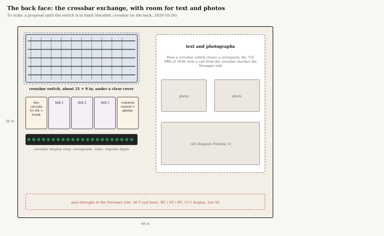
The layout at the top of this volume is a first proposal, drawn to scale. The switch sits upper left, at eye level, under its own clear cover, where a visitor can see the bars rock and the verticals snap in. Below it are five relay plates: the line circuits and trunk, one plate per link, and the common control with the link allotter. Each plate is labelled, so a visitor can match a plate’s clicking to the stage of the call. Below them is the display strip (Volume 3 lists what it watches). The right-hand third holds the text and photographs: how a crosspoint closes, the 755 PBX of 1938, and how a call from this side reaches the Strowger side. Along the bottom, pass-throughs carry power, ringing and tones, the display supply and line 66 through the panel.
Everything is a proposal until the switch is in hand: its real size, weight and mounting decide the rest.
4.3 Shared Power, Ringing and Tones
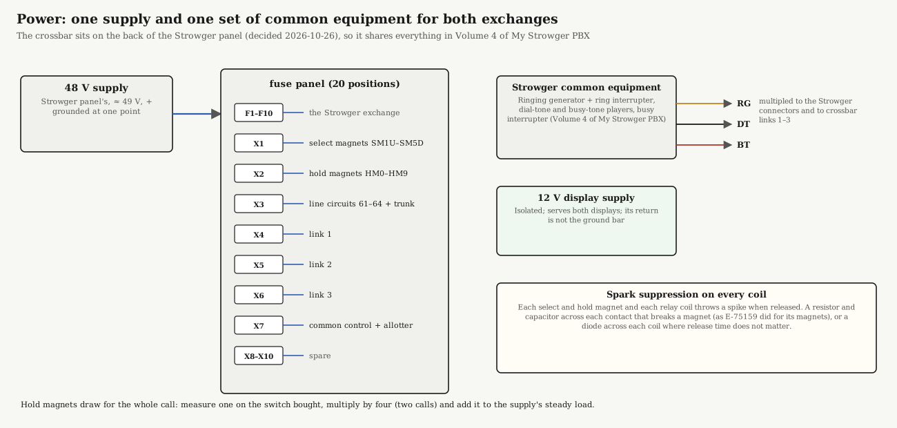
My Strowger PBX, Volume 4 designed the common equipment for the Strowger exchange. The crossbar exchange simply takes its share:
- 48 V supply. The same supply, about 49 V with the positive side grounded at one point. Check the switch’s magnets first: the 755A ran from a storage battery of “18 to 25 volts” (Bell System Practice 550-550-110, General Description, 755A PBX (1937)), so a switch from a 755A may have 24-volt magnets, which would need a 24 V supply of their own or series resistors. The 756A ran on 48 V (Bell Laboratories Record, December 1957), so a Bell switch is expected to have 48 V magnets; confirm on the switch bought.
- Ringing. The crossbar links’ RG lead is multipled to the same ringing lead as the Strowger connectors, ringing on battery through the same interrupter, so the links’ ring-trip relays work the same way.
- Dial tone and busy tone. The links take DT and BT from the same leads. A crossbar caller and a Strowger caller hear the same tones, which keeps the two exchanges feeling like one system.
- Display supply. The isolated 12 V supply serves both displays.
Sharing ringing has one limit worth checking: two calls can ring at once on each exchange, so the generator must ring up to four bells at a time. The current-production generators in the Strowger sourcing notes are rated for several; check the one bought.
4.4 Fuses
The Strowger fuse panel’s ten positions are already assigned, with two kept for the phase-2 selectors. The crossbar exchange needs seven more:
Table 1 — The Strowger fuse panel's ten positions are already assigned, with two kept for the phase-2 selectors. The crossbar exchange needs seven more
| Fuse | Load |
|---|---|
| X1 | select magnets SM1U–SM5D |
| X2 | hold magnets HM0–HM9 |
| X3 | line circuits 61–64 and the trunk circuit |
| X4–X6 | links 1–3 |
| X7 | common control and link allotter |
So the panel needs twenty positions: a 20-position telecom fuse panel in place of the 10-position one (the sourcing notes found a 20-position rack version of the same family), or a second small panel beside the first. The fuse alarm of both exchanges goes to the same red lamp, on the Strowger face, with a second lamp on the back so a visitor on either side sees it.
4.5 Driving the Magnets
Two kinds of load. A select magnet operates for a fraction of a second at a time, once per connection. A hold magnet stays operated for the whole call: each held crosspoint needs its vertical’s hold magnet in (sourcing notes, after US 3,400,225). With two calls up, four hold magnets draw steadily, unlike a Strowger switch, whose magnets draw only while stepping. Before trusting the shared supply, measure one hold magnet’s current on the switch bought, multiply by four, and add the links’ relays and the Strowger side’s steady load. The proposed supply’s 10.5 A should leave plenty of room, but this is the measurement that confirms it.
Spark suppression. Every magnet and relay coil throws a voltage spike when its circuit opens, and the contact that opens it arcs. The 1944 PAX of circuit E-75159 dealt with this with capacitors “connected from ground in multiple with the operating circuits of the finder and connector motor magnets … thru 125 [ohm] resistors,” which “prevent excessive sparking at the contacts … when the circuits to the motor magnets are opened” (E-75159). The same resistor-and-capacitor network suits every contact here that breaks a select or hold magnet. A diode across a coil suppresses the spike completely but slows the release, so use one only where release time does not matter.
One select magnet at a time. Only one select magnet may operate at a time, and it must stay in until the hold magnet has pulled in (Volume 3). The common control enforces this with a chain of contacts: no select magnet can be energised unless every other select magnet’s off-normal springs are at normal.
4.6 Timing in the Control Circuits
The crossbar control is less a matter of timing than of waiting. Each step of the common control’s sequence (Volume 3) begins only when the switch’s own off-normal springs report that the step before has happened: bar rotated, vertical in, link’s hold ground on. That makes it tolerant of slow or tired magnets: a sluggish bar simply takes a little longer.
Timing is still needed in three places, all with ordinary slow relays, as in the Strowger connector:
- The link’s B relay must be slow to release, so that it stays operated through the breaks of the dial pulses but drops when the caller hangs up.
- The register must know when a digit has ended: a slow-release relay that stays operated while pulses are arriving and releases in the pause between digits.
- A time-out in the common control, so that a step that never reports (a stuck bar, a broken spring) releases the attempt rather than holding the common control forever. The 756A’s marker did this with a second trial and an alarm (Bell Laboratories Record, January 1959); a single slow relay and a lamp are enough here.
4.7 The Bring-Up Controller
The relay circuits take time to build, and the switch should be proved before any of them exists. The bring-up controller of Volume 2 (item 9.1) does that:
- Drivers. A board of relay outputs, one per magnet: ten select magnets and ten hold magnets. Using relays as the drivers keeps the microcontroller isolated from the 48 V side. Each relay contact closes a magnet’s circuit through the X1 or X2 fuse, with the spark suppressor across the contact.
- Feedback. The bars’ and verticals’ off-normal springs read through opto-isolators, the same coil-tap circuit as the Strowger display (My Strowger PBX, Volume 5), so the controller sees exactly what the common control will see.
- Tests. Operate each select magnet alone; then each crosspoint in turn (select, hold, release select, check contacts with a meter, release hold); then two crosspoints in one row, as a link holds them; then every off-normal spring.
Once the switch is proved, the controller can stand in for the common control while the line and link circuits are built and tested, and be retired when the relay common control works. The order is in Volume 3, “Wiring It Up, in Order.”
4.8 Safety on a Panel Seen from Both Sides
Putting the crossbar on the back means both faces of the panel are public. The Strowger side’s safety rules (My Strowger PBX, Volume 4) apply to the back as well:
- Ringing reaches the back. Every link circuit switches RG, about 86–100 V RMS on top of −48 V. The link plates and their terminals go behind a clear guard, like the switch.
- The lock-out switch removes ringing from both exchanges, since they share the generator.
- The pass-throughs are bushed and strain-relieved, so a cable cannot chafe on the panel’s edge.
- Both faces must be reachable for maintenance without unloading the panel: the rolling frame keeps the back clear, and the panel can be turned end-for-end on its wheels.
4.9 In the Reference Library
- E-75159 10-Line Isolated PAX: spark suppression across magnet circuits.
- Bell Laboratories Record, January 1959: the 756A’s marker, its second trial and its alarms.
- BSP 551-147-210: 756A service options, including its power plant.
- AE Training Bulletin 812: office power, fuses and alarms.
Sources
- Bell System Practice 550-550-110, General Description, 755A PBX, issue 1 (1937), Reference Library.
- Automatic Electric, circuit explanation E-75159 (1944), spark suppressors S1 and S2, Reference Library.
- O. H. Williford, “A Modern Crossbar PBX”, Bell Laboratories Record, December 1957; R. D. Williams, “Crossbar Circuitry for a Small PBX”, January 1959; Reference Library.
- Hold-magnet current: the sourcing notes, citing US 3,400,225.
- My Strowger PBX, Volume 4 (power, ringing, tones, safety) and Volume 5 (the coil tap), on this site.